Prerequisite. Prerequisites: Chapter 3’s arriving mass, energy, momentum, footprint and impact history.
先修知识。 前提:第三章的到达质量、能量、动量、作用面积及撞击历程。
1. Intended-interface release
1. 目标界面释放
Connect the arriving jet to film deformation, crack growth and departure. Useful transfer ends with intact attachment at the intended receiver location. Chapter 3 supplies velocity, mass, momentum, energy, footprint and arrival history. Specify the exposed surface carrying that load. The output is opening and fracture at the release interface. These surfaces can lie at different stack positions.
Use Cartesian coordinates with the initial film horizontal. Positive vertical points along intended departure. Start the film at rest with specified adhesion and pre-existing delamination. Plate examples fix the donor reference face. A moving donor needs momentum and power balances. Pressure compresses the exposed face. Interface opening depends on relative face separation. Either prescribe fluid traction or resolve compatible fluid–solid velocities and opposite tractions. Count the interface load once.
Coupled cavity thermodynamics, bulging and fracture; an outgoing jet need not exist.
耦合腔体热力学、鼓起与断裂;不一定存在出射射流。
Intact PVC blocks liquid passage. An incident jet first loads PVC. Direct film loading requires an actual opening or rupture. Sealed cavities and open pockets have different force paths. Appendix A compares these hydrogel architectures.
完整 PVC 阻挡液体穿透,入射射流首先加载 PVC。直接加载薄膜需要实际开口或破裂。密闭空腔与开放液腔具有不同传力路径。附录 A 比较这些水凝胶结构。
Symbols and model limits
符号与模型范围
Symbol
符号
Physical meaning
物理意义
SI units
SI 单位
Role and convention
作用与约定
nf
Solid-to-liquid unit normal
固体指向液体的单位法向
1
At a film with liquid below, it points downward; pressure traction can still push upward.
对于下方接触液体的薄膜,该法向向下;压力牵引仍可向上推动。
tl
Liquid traction on the solid
液体施加于固体的牵引
Pa
Stress contracted with the specified normal at the exposed face.
外露面上应力与指定法向的收缩。
p
Liquid absolute pressure
液体绝对压力
Pa
Acts compressively on the exposed face; release-interface opening depends on structural motion.
对外露面产生压缩作用;释放界面张开取决于结构运动。
q
Signed transverse applied load
带符号横向外加载荷
Pa
Positive in the upward film-opening direction; distinguishes applied pressure from net reactions.
沿薄膜向上张开方向取正;区分外加压力与净反力。
w
Film transverse displacement
薄膜横向位移
m
Positive upward; its spatial profile determines bending and interface opening.
向上取正;其空间分布决定弯曲与界面张开。
w˙
Film transverse velocity
薄膜横向速度
m s⁻¹
First time derivative of displacement; enters kinetic energy and power.
位移的一阶时间导数;进入动能及功率计算。
w¨
Film transverse acceleration
薄膜横向加速度
m s⁻²
Second time derivative of displacement; gives the areal inertial load.
位移的二阶时间导数;给出单位面积惯性载荷。
hf
Film thickness
薄膜厚度
m
Controls areal mass and the cubic thickness dependence of bending rigidity.
控制面质量及弯曲刚度对厚度的三次方依赖。
ρf
Film mass density
薄膜质量密度
kg m⁻³
Solid density used in areal mass; distinct from the incoming liquid density.
面质量采用的固体密度;与入射液体密度不同。
Ef
Film Young’s modulus
薄膜杨氏模量
Pa
Elastic stiffness for the declared thin-plate constitutive control.
指定薄板本构对照的弹性刚度参数。
νf
Film Poisson’s ratio
薄膜泊松比
1
Relates transverse and longitudinal elastic strains within the adopted isotropic model.
在所采用各向同性模型中关联横向与纵向弹性应变。
Df
Film bending rigidity
薄膜弯曲刚度
N m
Combines modulus, thickness and Poisson’s ratio; not a diffusivity or strain-rate tensor.
结合模量、厚度与泊松比;不是扩散率或应变率张量。
Γ
Practical interfacial fracture energy
实际界面断裂能
J m⁻²
Resistance per newly released area under the relevant mode and rate; not a geometric surface here.
相关模式与速率下单位新释放面积的阻力;此处不是几何曲面。
G
Mechanical energy-release rate
力学能量释放率
J m⁻²
Energy available per incremental crack area; compared with fracture resistance.
单位增量裂纹面积可获得的能量;与断裂阻力比较。
Tmax
Peak tensile cohesive traction
峰值拉伸内聚牵引
Pa
Local cohesive strength; not equivalent to interfacial fracture energy.
局部内聚强度;不等同于界面断裂能。
δ
Relative opening of the release interface
释放界面相对张开量
m
Relative displacement across the bonded interface; not the absolute displacement of one film.
粘接界面两侧的相对位移;不是某一薄膜的绝对位移。
a
Circular released/blister radius
圆形释放/鼓泡区域半径
m
Defines the crack front and domain size in the clamped circular-plate control.
在固支圆板对照中定义裂纹前缘与区域尺度。
t
Time
时间
s
Independent coordinate for pulse loading, inertia and fracture evolution.
脉冲受载、惯性及断裂演化的独立坐标。
∇∥
Film-plane spatial gradient
薄膜平面空间梯度
m⁻¹
Differentiates within the plate plane; it is an operator rather than a material parameter.
在薄板平面内求导;是算子,而非材料参数。
2. Fluid stress and solid loading
2. 流体应力与固体加载
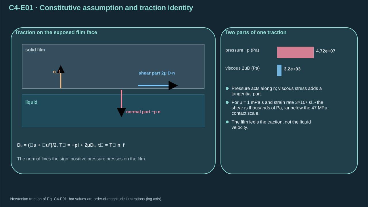
Step 1 — Adopt Newtonian liquid stress. Orient the normal from solid into liquid. Stress contracted with this normal gives liquid traction on solid. For liquid below a film, the normal points down. Positive pressure pushes the film up while compressing its exposed face. Opening another interface requires deformation and relative motion.
nf is the unit solid-to-liquid normal (dimensionless)
nf为固体指向液体的单位法向(无量纲)
tl is traction on the solid (Pa)
tl为固体上的牵引(Pa)
Conventions and conditions.∇ is the spatial gradient (m⁻¹); superscript T transposes a tensor; Subscripts u, l and f label velocity strain, liquid and film surface.
(C4-E01) · Constitutive assumption and traction identity
本构假设与牵引恒等式
Du=2∇u+(∇u)T,Tl=−pI+2μDu,tl=Tlnf
Pressure and shear act at the exposed film face; the drawn normal fixes the traction sign.
压力与剪切作用于薄膜外露面;所画法向决定牵引符号。
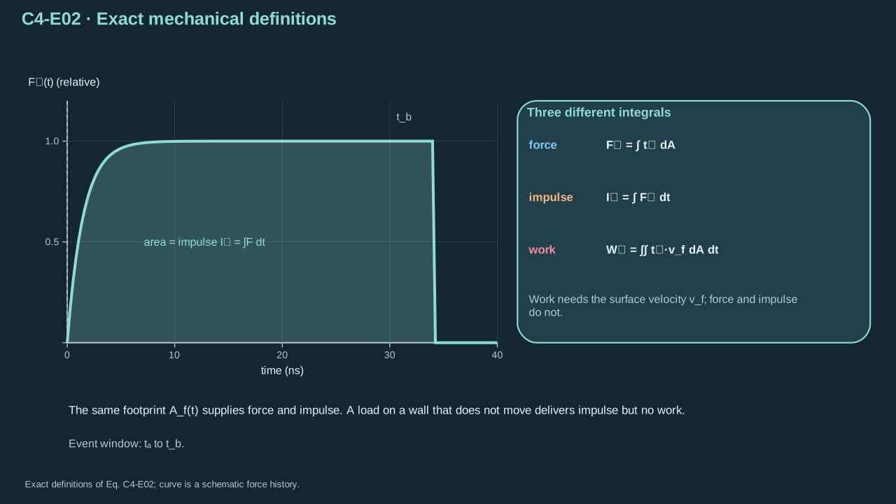
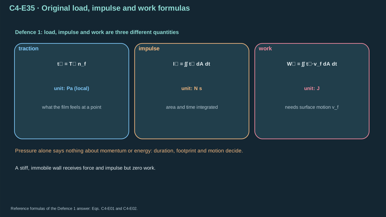
Step 2 — Integrate traction over area for force. Integrate force over time for impulse. Dot traction with surface velocity before integrating work. Pressure, impulse and work have units Pa, N s and J. A nearly rigid surface can receive high stress and impulse with little displacement work.
步骤 2——对面积积分牵引得到力,对时间积分力得到冲量。求功时先将牵引与表面速度点乘。压力、冲量与功单位分别为 Pa、N s 和 J。近刚性表面可承受大应力及冲量,同时位移功很小。
Symbols before Eq. (C4-E02).
式(C4-E02)前的符号定义。
First individual definition第一项单独定义
Second individual definition第二项单独定义
Af(t) is the loaded solid surface (m²)
Af(t)为固体受载表面(m²)
dA its surface-area element (m²), and ∫ denotes integration over the indicated surface or time
dA为表面积微元(m²),∫表示对所示表面或时间积分
tl is applied liquid traction (Pa)
tl为液体施加的牵引(Pa)
Fl its resultant (N)
Fl为其合力(N)
Il its impulse (N s)
Il为其冲量(N s)
Wl work delivered to the solid (J)
Wl为传入固体的功(J)
vf is local solid surface velocity (m s⁻¹)
vf为固体表面局部速度(m s⁻¹)
ta — Load-event start time (s)
ta — 载荷事件开始时刻(s)
tb — Load-event end time (s)
tb — 载荷事件结束时刻(s)
t — Time (s)
t — 时间(s)
dt — Time integration element (s)
dt — 时间积分微元(s)
Conventions and conditions. The vector dot product projects force onto velocity; Subscripts l and f label liquid and film; ta<tb fixes the integration interval..
The same footprint supplies force and impulse, but surface motion is additionally required for work.
同一作用范围决定力与冲量,而求功还需要表面运动信息。
3. Transient film mechanics
3. 瞬态薄膜力学
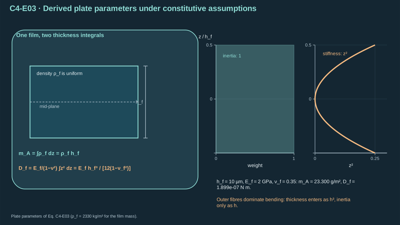
Step 3 — Adopt a homogeneous isotropic Kirchhoff–Love plate. Assume elastic plane stress, small strain, small slope and thinness relative to deformation length. Through-thickness density integration gives areal mass. Bending stress integration gives stiffness with thickness moment thickness³/12. A bonded laminate needs a common neutral surface and laminate stiffness.
Areal inertia and bending stiffness come from different thickness integrals.
面惯性与弯曲刚度来自不同的厚度积分。
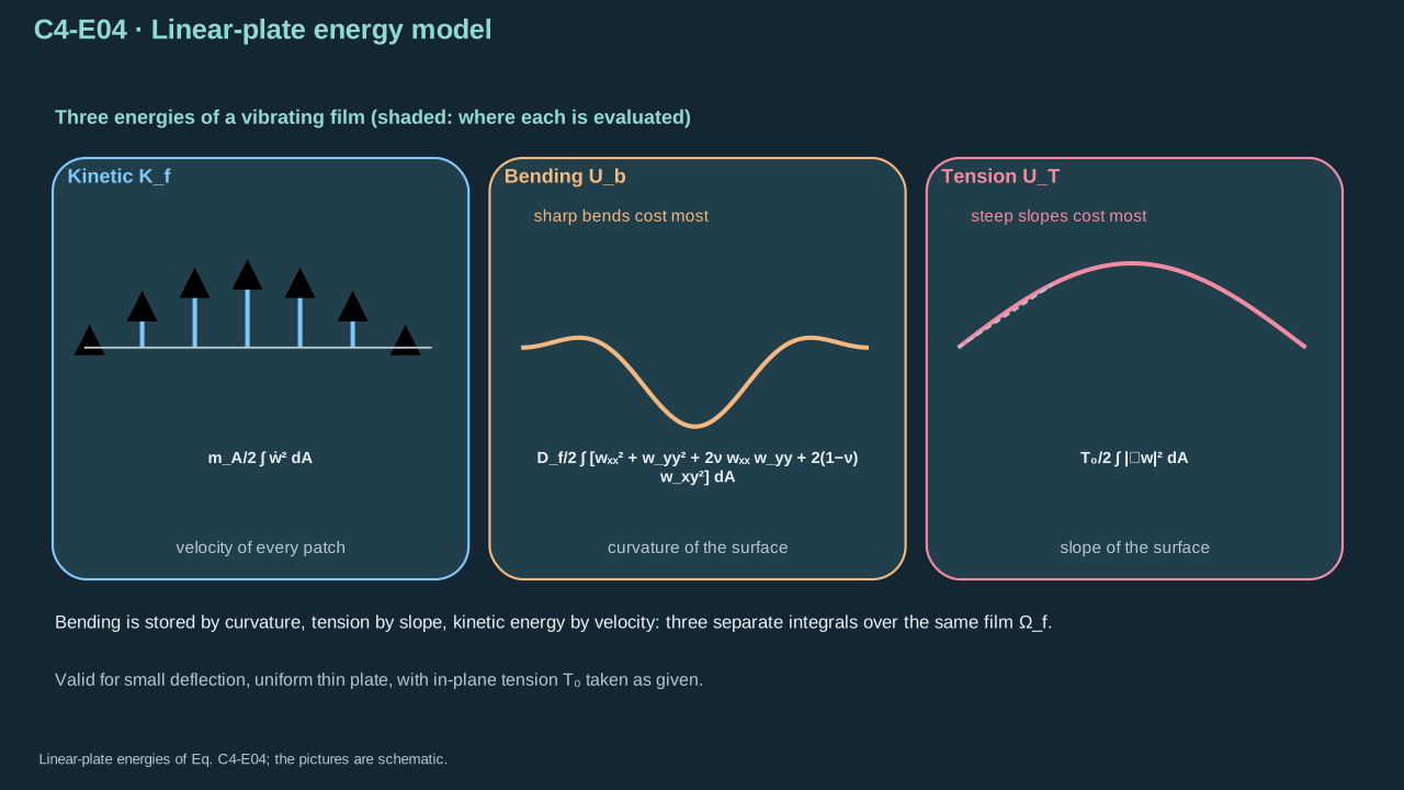
Step 4 — Write kinetic, bending and pretension energies. Curvature is the displacement’s second spatial derivative. Poisson ratio couples the two curvature directions and twist. Hold pretension uniform; its energy penalizes slope. Shape stores elastic energy, while velocity carries kinetic energy.
T0≥0 prescribed isotropic tensile force per edge length (N m⁻¹)
T0≥0为给定各向同性单位边长拉力(N m⁻¹)
Kf — Film kinetic energy (J)
Kf — 薄膜动能(J)
Ub — Plate bending energy, not bubble internal energy in this unit (J)
Ub — 板弯曲能,本单元不表示气泡内能(J)
UT — Stored pretension energy (J)
UT — 预张力储能(J)
Conventions and conditions. A dot differentiates in time; subscripts xx,yy,xy differentiate twice in the indicated coordinates, giving curvatures (m⁻¹); ∇∥ is the in-plane gradient; ∣∣ denotes Euclidean magnitude; ∫ denotes area integration; Labels f, b, T identify film, bending and tension.
Bending energy is stored by curvature; inertia depends on velocity.
曲率储存弯曲能,速度决定惯性动能。
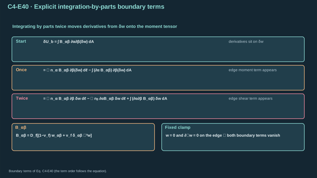
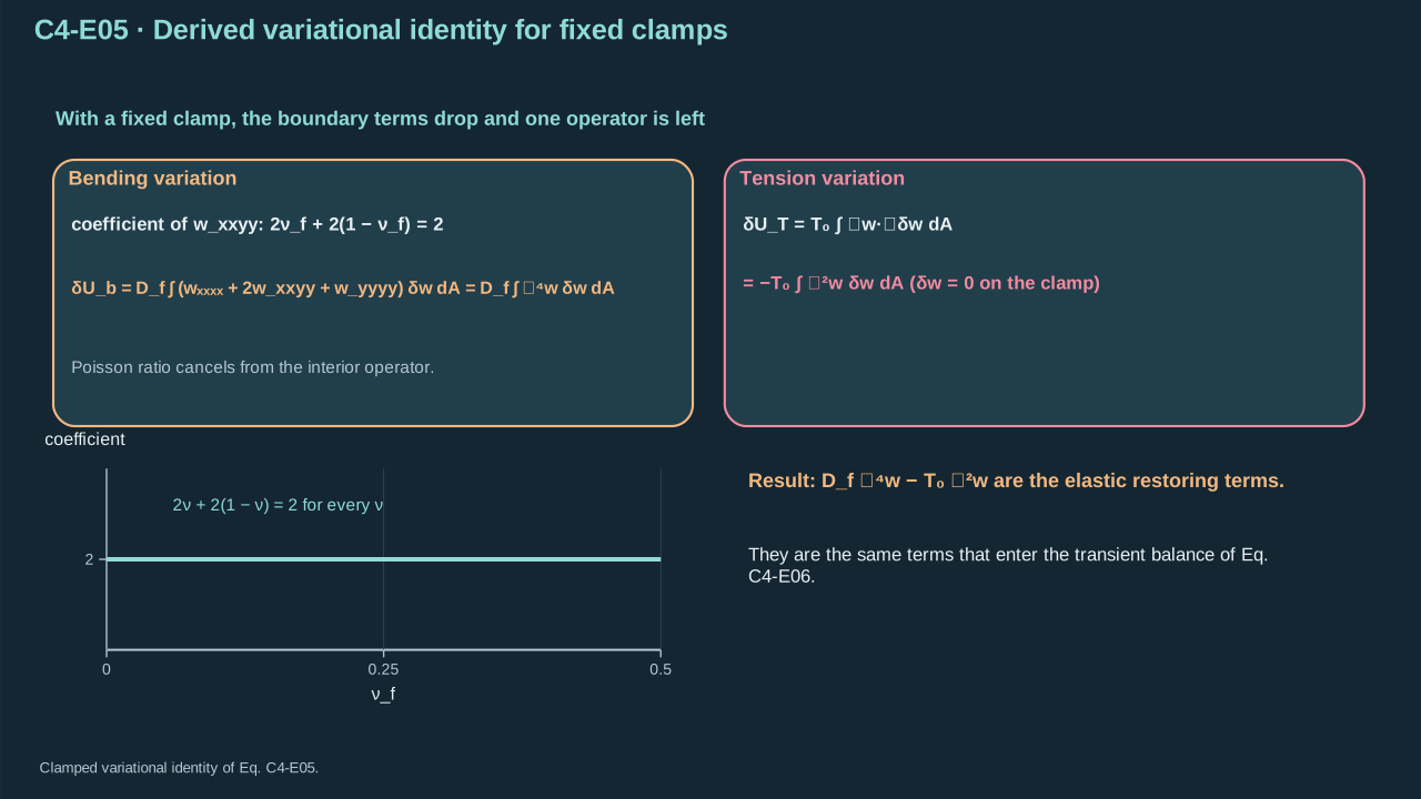
Step 5 — Vary displacement at a fixed clamped boundary. Integrate bending terms by parts twice. Displacement variation and its normal slope vanish at the clamp, eliminating boundary terms. Integrate tension once to obtain minus the Laplacian. Every transverse-balance term has pressure units.
Ωf is the smooth reference film plane (m²), ∂Ωf its boundary
Ωf为光滑薄膜参考平面(m²),∂Ωf为其边界
dA area element (m²)
dA为面积微元(m²)
dℓ boundary arc-length element (m)
dℓ为边界弧长微元(m)
w is displacement (m)
w为位移(m)
δw an admissible infinitesimal variation (m)
δw为容许无穷小变分(m)
δUb — Bending-energy variation (J)
δUb — 弯曲能变分(J)
δUT — Pretension-energy variation (J)
δUT — 预张力能变分(J)
α — Cartesian in-plane direction index, taking 1 or 2 (dimensionless)
α — 取 1 或 2 的笛卡尔面内方向指标(无量纲)
β — Cartesian in-plane direction index, taking 1 or 2 (dimensionless)
β — 取 1 或 2 的笛卡尔面内方向指标(无量纲)
wαβ=∂α∂βw is curvature (m⁻¹)
wαβ=∂α∂βw为曲率(m⁻¹)
Df is bending stiffness (N m)
Df为弯曲刚度(N m)
νfPoisson’s ratio
νf为泊松比
T0 pretension (N m⁻¹)
T0为预张力(N m⁻¹)
Bαβ the bending-energy tensor conjugate to curvature (N)
Bαβ为与曲率共轭的弯曲能张量(N)
δαβ is the dimensionless Kronecker identity, distinct from variation notation
δαβ为无量纲Kronecker单位张量,与变分记号不同
nα — Component of the outward in-plane unit normal (dimensionless)
nα — 面内外单位法向的分量(无量纲)
nβ — Component of the outward in-plane unit normal (dimensionless)
nβ — 面内外单位法向的分量(无量纲)
0 is zero gradient (dimensionless)
0为零梯度(无量纲)
Conventions and conditions.∂α is coordinate differentiation (m⁻¹); ∂n its derivative; ∇∥ and ∇∥2 are in-plane gradient and Laplacian; ∫,∮ denote area and closed-boundary integrals; ⇒ uses zero tangential derivative of an identically zero boundary variation plus the prescribed zero normal derivative; ∑α,β=12 sums all four index pairs..
BαβδUbδUTδw=0,∂nδw=0=Df[(1−νf)wαβ+νfδαβ∇∥2w],=α,β=1∑2∫ΩfBαβ∂α∂β(δw)dA=α,β=1∑2∮∂ΩfnαBαβ∂β(δw)dℓ−α,β=1∑2∫Ωf(∂αBαβ)∂β(δw)dA=α,β=1∑2∮∂Ωf[nαBαβ∂β(δw)−nβ(∂αBαβ)δw]dℓ+α,β=1∑2∫Ωf(∂β∂αBαβ)δwdA,=T0∮∂Ωfδw∂nwdℓ−T0∫Ωfδw∇∥2wdA,⟹∇∥δw=0on the fixed clamp.
Two integrations by parts expose the boundary moment and shear terms before they are removed.
两次分部积分先明确显示边界弯矩与剪力项,再依据条件将其消去。
Symbols before Eq. (C4-E05).
式(C4-E05)前的符号定义。
First individual definition第一项单独定义
Second individual definition第二项单独定义
δw is a displacement variation (m)
δw为位移变分(m)
Ub — Plate bending energy, not bubble internal energy in this unit (J)
Ub — 板弯曲能,本单元不表示气泡内能(J)
UT — Stored pretension energy (J)
UT — 预张力储能(J)
Df is bending stiffness (N m)
Df为弯曲刚度(N m)
νf is dimensionless Poisson’s ratio
νf为无量纲泊松比
T0 is uniform pretension (N m⁻¹)
T0为均匀预张力(N m⁻¹)
w is transverse displacement (m)
w为横向位移(m)
x — First Cartesian in-plane coordinate (m)
x — 第一笛卡尔面内坐标(m)
y — Second Cartesian in-plane coordinate (m)
y — 第二笛卡尔面内坐标(m)
Ωf is film area (m²)
Ωf为薄膜面积(m²)
dA is its element (m²)
dA为面积微元(m²)
Conventions and conditions. Subscripts xxxx,xxyy,yyyy denote the indicated fourth derivatives (m⁻³); ∇∥2=∂x2+∂y2 is the in-plane Laplacian; ∇∥4 is that Laplacian applied twice; ∫ is area integration; The variations and their normal slopes vanish at a clamped boundary; δ denotes an infinitesimal admissible variation, not physical crack opening here.
A fixed clamp removes the boundary virtual-work terms.
固定夹持边界使边界虚功项消失。
Symbols before Eq. (C4-E06).
式(C4-E06)前的符号定义。
First individual definition第一项单独定义
Second individual definition第二项单独定义
w(x,t) is film displacement in the positive departure direction (m)
w(x,t)为沿正离开方向的薄膜位移(m)
x=(x,y) is in-plane position (m)
x=(x,y)为面内位置(m)
t time (s)
t为时间(s)
w˙ — Film transverse velocity (m s⁻¹)
w˙ — 薄膜横向速度(m s⁻¹)
w¨ — Film transverse acceleration (m s⁻²)
w¨ — 薄膜横向加速度(m s⁻²)
mA is areal mass (kg m⁻²)
mA为面密度(kg m⁻²)
Df bending stiffness (N m)
Df为弯曲刚度(N m)
T0≥0 pretension (N m⁻¹)
T0≥0为预张力(N m⁻¹)
pload is net applied transverse traction projected positively (Pa)
pload为沿正方向投影的净外加横向牵引(Pa)
tcoh≥0 is an opening-resisting cohesive traction magnitude (Pa)
tcoh≥0为抵抗张开的内聚牵引幅值(Pa)
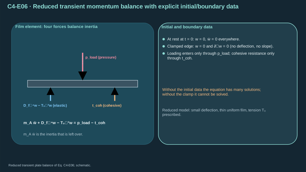
Conventions and conditions.∇∥2 is in-plane Laplacian (m⁻²), and ∇∥4 its square; ∂n differentiates along the outward in-plane boundary normal; Initial zero is displacement or velocity according to its row; Labels load and coh identify applied and cohesive forces.
(C4-E06) · Reduced transient momentum balance with explicit initial/boundary data
含明确初始与边界数据的简化瞬态动量平衡
mAw¨+Df∇∥4w−T0∇∥2ww(x,0)=0,w˙(x,0)w=0,∂nw=pload−tcoh,=0,=0on a clamped edge.
Film acceleration balances applied traction, elastic restoring forces and cohesive resistance.
薄膜加速度由外加牵引、弹性恢复力与内聚阻力的平衡决定。
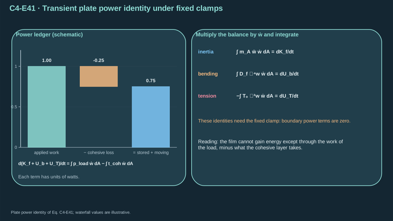
The fixed clamp also has zero velocity and normal velocity slope. Multiply the plate equation by velocity and integrate. Inertia differentiates kinetic energy. Two bending integrations by parts differentiate bending energy. One tension integration differentiates pretension energy. Cohesive power removes energy from plate motion. The interface law partitions recoverable and irreversible parts.
Ub — Plate bending energy, not bubble internal energy in this unit (J)
Ub — 板弯曲能,本单元不表示气泡内能(J)
UT — Stored pretension energy (J)
UT — 预张力储能(J)
t is time (s)
t为时间(s)
Conventions and conditions.d/dt is its derivative; ∇∥2 is planar Laplacian and ∇∥4 its square; ∫ is area integration; The derivatives are valid for the stated constant parameters and sufficiently regular fields at a fixed clamp with zero velocity and normal velocity slope; Every row has power units W; f, b, T, load and coh label film, bending, tension, applied and cohesive.
The transient plate equation conserves power between applied work, motion, shape and interface response.
瞬态薄板方程在外加功、运动、形状与界面响应之间保持功率守恒。
This is an exact balance within the reduced plate assumptions. Bending units are N m × m⁻³ = Pa. Tension units are N m⁻¹ × m⁻¹ = Pa. Zero mass gives quasistatic balance. Zero stiffness, tension and cohesion gives free areal acceleration. Large slope, stretching, plasticity, anisotropy, finite thickness or contact needs refinement. The cited static benchmark agrees with the stiffness formulation. This derivation retains inertia. MIT plate benchmark
这是约化板假设内的精确平衡。弯曲单位为 N m × m⁻³ = Pa,张力单位为 N m⁻¹ × m⁻¹ = Pa。质量取零得到准静态平衡,刚度、张力及内聚力取零得到自由面加速度。大斜率、拉伸、塑性、各向异性、有限厚度或接触需细化。所引静态基准与刚度形式一致,本推导保留惯性。MIT 板基准
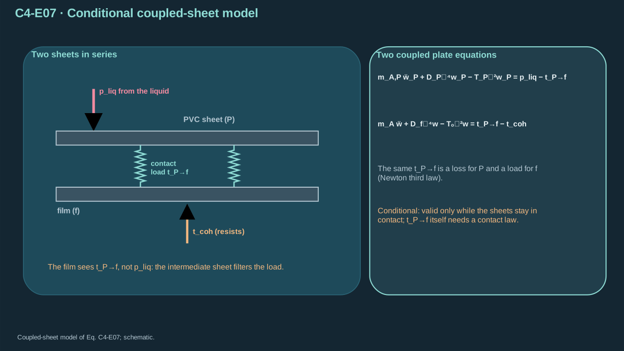
Step 6 — Include PVC mechanics. Give each sheet its own areal mass, stiffness and support. Transmitted traction acts oppositely on the sheets by Newton’s third law. Determine it through contact or bond closure. A fully bonded laminate additionally requires in-plane compatibility and composite stiffness.
Conventions and conditions. double dots are accelerations (m s⁻²); ∇∥2 is the in-plane Laplacian and ∇∥4 its square; P labels PVC, f film, A areal, liq liquid and coh cohesion; the arrow labels the transmission direction; Each sheet has its actual initial and support conditions; No value of transmitted traction is supplied without an additional contact/bond closure.
The PVC-to-film load follows intermediate-sheet motion and contact.
PVC传向薄膜的载荷由中间片层运动与接触决定。
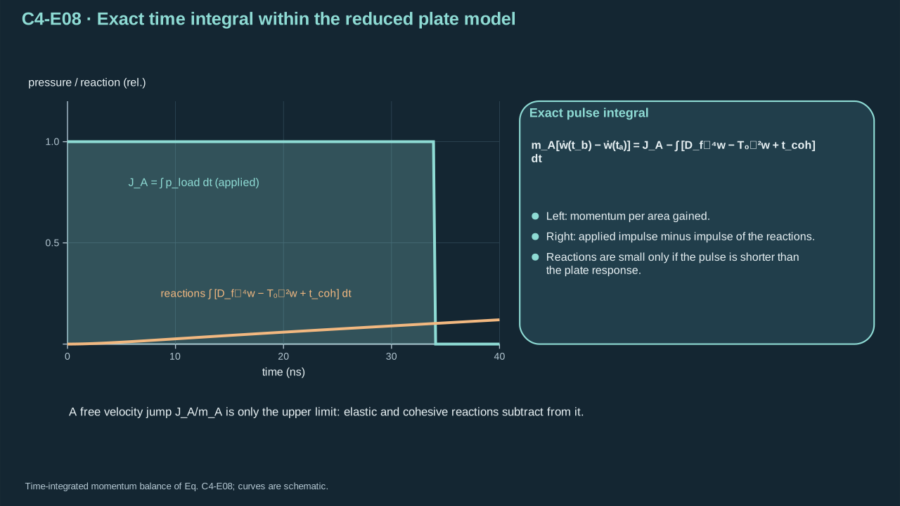
Step 7 — Integrate the film equation over the pulse. Retain restoring and cohesive impulses. A free velocity jump requires both small relative to applied impulse. A film bonded to rigid donor across the footprint fails that condition. Count resolved fluid inertia once.
Conventions and conditions.∇∥2 and ∇∥4 are the in-plane Laplacian and its square; ∫ integrates the actual local load/response during the pulse; Labels A, f, load and coh mean areal, film, applied and cohesive.
Pulse integration exposes the reactions that can invalidate a free velocity jump.
脉冲积分明确显示哪些反作用冲量会使自由速度跃变失效。
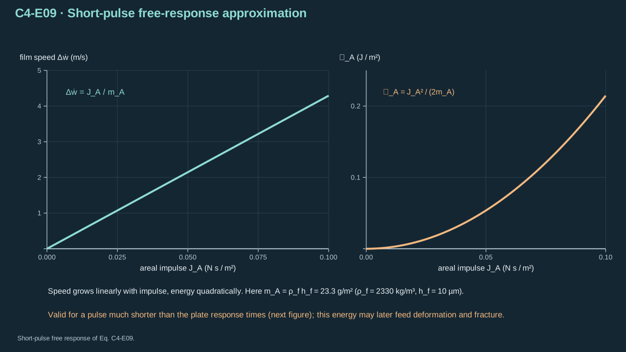
Symbols before Eq. (C4-E09).
式(C4-E09)前的符号定义。
First individual definition第一项单独定义
Second individual definition第二项单独定义
Δw˙ is the film velocity change from rest (m s⁻¹)
Δw˙为薄膜从静止开始的速度变化(m s⁻¹)
JA is local applied impulse per area (Pa s)
JA为局部单位面积外加冲量(Pa s)
mA>0 film areal mass (kg m⁻²)
mA>0为薄膜面密度(kg m⁻²)
EA resulting kinetic energy per area (J m⁻²)
EA为所得单位面积动能(J m⁻²)
Conventions and conditions.≃ marks negligible restoring/cohesive impulse during the pulse, not guaranteed transmission through an adhered stack; Subscript A labels quantities per area; Δ denotes final-minus-initial difference, and a dot is a time derivative.
Impulse creates film kinetic energy that may subsequently feed deformation and fracture.
冲量产生薄膜动能,之后才可能转入变形与断裂。
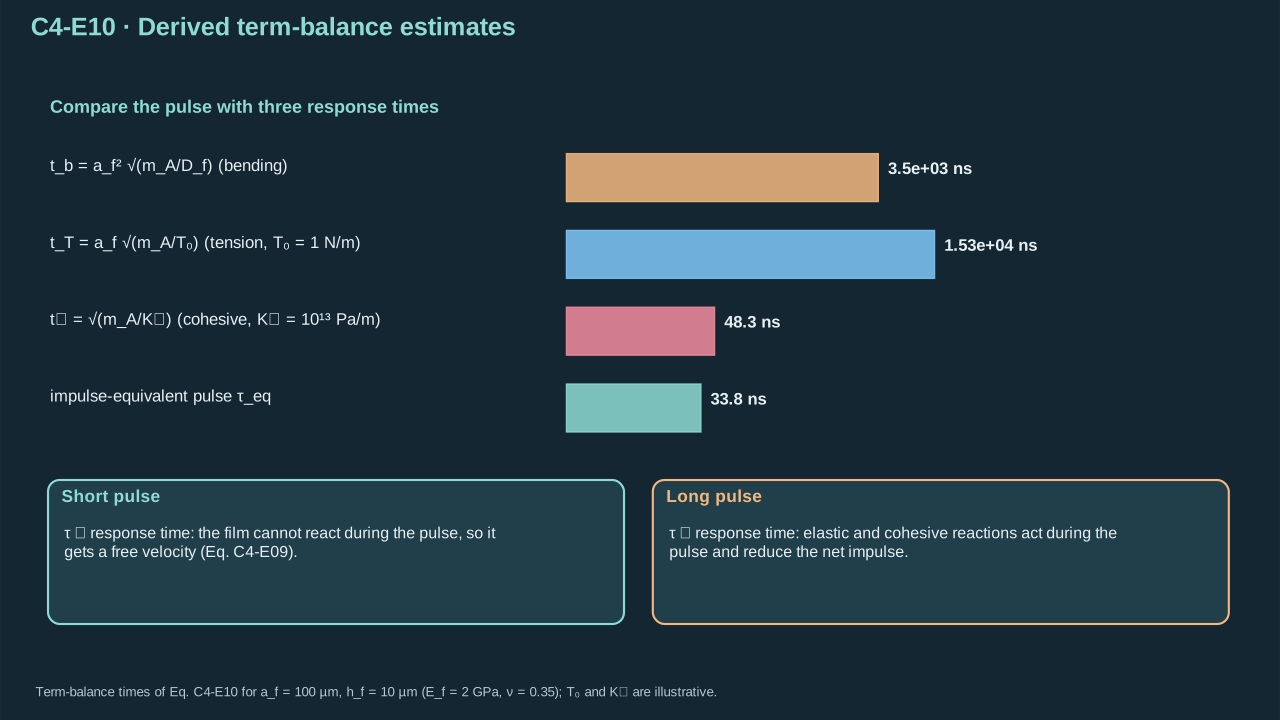
Balance inertia with bending and tension over the deformation length. Compare the resulting response times with pulse duration. Small-opening cohesive stiffness gives a third time. Slow duration alone leaves equilibrium unresolved when pulse edges or crack growth are rapid.
tnscale — Normal-cohesion response-time estimate (s)
tnscale — 法向内聚响应时间估计(s)
af>0 is lateral deformation length (m)
af>0为横向变形长度(m)
mA>0 areal mass (kg m⁻²)
mA>0为面密度(kg m⁻²)
Df>0 bending stiffness (N m)
Df>0为弯曲刚度(N m)
T0>0 pretension (N m⁻¹)
T0>0为预张力(N m⁻¹)
Kn>0 small-opening normal cohesive stiffness (Pa m⁻¹)
Kn>0为小张开法向内聚刚度(Pa m⁻¹)
Conventions and conditions. superscript scale labels estimates and subscripts b, T, n identify the restoring mechanisms; is the positive root; If pretension or cohesion is absent, its corresponding timescale is omitted rather than divided by zero.
Pulse duration must be compared with the response scales of the actual load path.
脉冲持续时间须与实际传力路径的响应尺度比较。
4. Interface strength and fracture work
4. 界面强度与断裂功
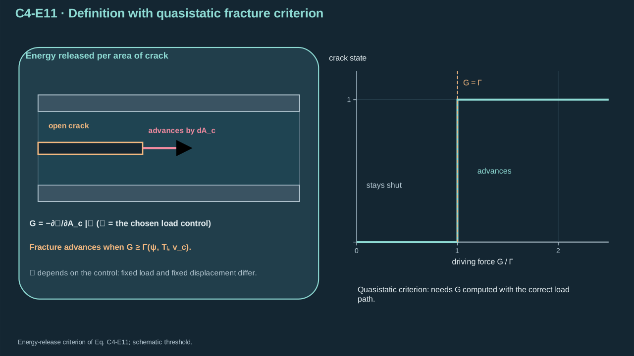
Step 8 — Specify loading control before crack driving force. Peak tensile traction is local strength in Pa. Reversible adhesion work is a surface-energy difference. Practical fracture energy includes dissipation and has units J m⁻². For quasistatic conservative mechanics, differentiate potential by crack area at fixed source control. Mode mixture, temperature and crack speed can change resistance.
步骤 8——计算裂纹驱动力前规定加载控制。峰值拉伸牵引是 Pa 单位局部强度。可逆粘附功是表面能差。实际断裂能包含耗散,单位为 J m⁻²。准静态保守力学中,在固定源控制下对裂纹面积求势能导数。模态混合、温度及裂纹速度可改变阻力。
Symbols before Eq. (C4-E11).
式(C4-E11)前的符号定义。
First individual definition第一项单独定义
Second individual definition第二项单独定义
G is quasistatic energy-release rate (J m⁻²)
G为准静态能量释放率(J m⁻²)
P total mechanical potential including the external loading system (J)
P为包含外部加载系统的总力学势能(J)
Ac crack area (m²), and ∂/∂Ac a partial derivative
Ac为裂纹面积(m²),∂/∂Ac为偏导数
C labels the held loading control, such as pressure or displacement (—)
C标识保持不变的加载控制量,例如压力或位移,而非材料系数(—)
Γ is fracture resistance (J m⁻²)
Γ为断裂阻力(J m⁻²)
ψ mode-mixture parameter (dimensionless)
ψ为模态混合参数(无量纲)
Ti interface temperature (K)
Ti为界面温度(K)
vc crack-front speed (m s⁻¹)
vc为裂纹前沿速度(m s⁻¹)
Conventions and conditions. it is not a material coefficient; Subscripts c and i label crack and interface; The inequality is an energetic propagation criterion for the specified fracture model, not a sufficient transfer criterion.
约定与条件。 下标c与i表示裂纹及界面;此不等式是指定断裂模型的能量扩展判据,而非充分转印判据。
(C4-E11) · Definition with quasistatic fracture criterion
定义与准静态断裂判据
G=−∂Ac∂PC,G≥Γ(ψ,Ti,vc)
A crack is driven by energy per newly separated area, under a specified load control.
裂纹由每单位新分离面积的可用能量驱动,且加载控制必须明确。
Comparing pressure with fracture energy requires a deformation length and mechanical law. Competing paths include intended release, another bond’s failure and payload tearing. Feng et al. show how interface kinetics alter path competition. Measure rate and temperature dependence for the actual PFC stack. Their PDMS values require separate justification before reuse. [R10]
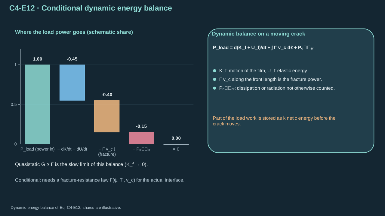
Retain kinetic energy during rapid fracture. The chosen crack-front balance includes elastic storage, inertia, fracture consumption and other loss. Count cohesive dissipation once through the selected fracture energy. Crack path still requires structural and interface equations.
Pload is mechanical power delivered to the solid (W)
Pload为传入固体的力学功率(W)
Kf its kinetic energy (J)
Kf为固体动能(J)
Uf its recoverable elastic energy including any recoverable interface energy (J), and d/dt the time derivative with t in s
Uf为可恢复弹性能,含任何可恢复界面能(J),d/dt为时间导数
Lc is the active crack-front line (—)
Lc为活跃裂纹前沿曲线(—)
dℓ is its arc-length element (m)
dℓ为弧长微元(m)
vc≥0 is front speed (m s⁻¹)
vc≥0为前沿速度(m s⁻¹)
Γfracture energy (J m⁻²)
Γ为断裂能(J m⁻²)
ψ dimensionless mode mixture
ψ为无量纲模态混合参数
Ti interface temperature (K)
Ti为界面温度(K)
Pother≥0 is additional nonfracture dissipation (W)
Pother≥0为其他非断裂耗散(W)
t — Time (s)
t — 时间(s)
Conventions and conditions.∫ integrates along the front; Labels load, f, c, i and other denote applied, solid film, crack, interface and remaining dissipative processes.
Dynamic loading can store kinetic energy before or during crack advance.
动态载荷可在裂纹扩展前或扩展中储存动能。
5. Circular blister benchmark
5. 圆形鼓泡基准
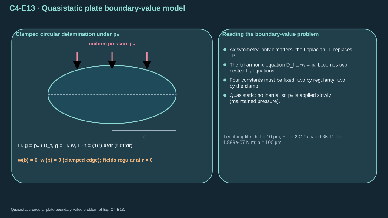
Step 9 — Define pressure-controlled delamination. A pre-existing circular crack lies beneath a thin isotropic plate. The bonded region clamps its edge. A reservoir maintains uniform positive pressure as radius varies. Omit inertia, pretension and stretching. Center displacement and curvature are regular without point force or singular moment. This benchmark has different loading from the transient jet array.
Conventions and conditions.d/dr and a prime denote radial differentiation; the operator at r=0 is its regular limit; Labels r, f and 0 denote radial operator, film/arbitrary function according to context, and maintained load; The two zero values prescribe edge displacement and slope.
Uniform pressure loads a clamped circular delamination with regular central fields.
均匀压力作用于边缘夹持的圆形脱层,中心场必须正则。
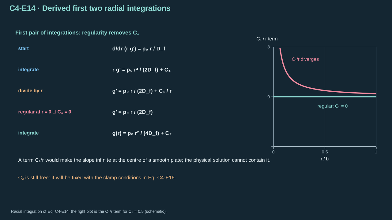
Step 10 — Solve the curvature sum. Multiply its radial Laplacian equation by radius and integrate. Divide by radius away from the center. Regular curvature gradient excludes the inverse-radius term. Integrate again for the constant curvature offset. The edge slope will determine it.
g(r)=Lrw is the curvature sum (m⁻¹), with a prime and d/dr denoting radial differentiation
g(r)=Lrw为曲率和(m⁻¹),撇号及d/dr表示径向求导
p0 is maintained pressure difference (Pa)
p0为恒定压差(Pa)
Df bending stiffness (N m)
Df为弯曲刚度(N m)
C1 — Curvature integration constant (m⁻¹)
C1 — 曲率积分常数(m⁻¹)
C2 — Curvature integration constant (m⁻¹)
C2 — 曲率积分常数(m⁻¹)
Lr is the radial Laplacian (m⁻²)
Lr为径向拉普拉斯算子(m⁻²)
w displacement (m)
w为位移(m)
Conventions and conditions.C1=0 follows from regular central curvature gradient and absence of a point load; the subscript 0 labels the maintained pressure, not the initial liquid pressure.
Regularity removes the singular integration constant before edge conditions are used.
在使用边缘条件之前,正则性先排除奇异积分常数。
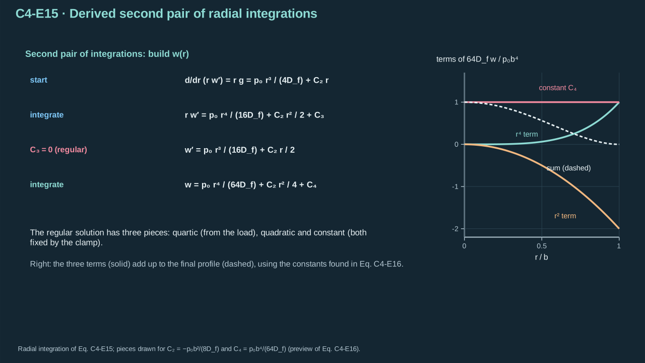
Step 11 — Integrate curvature to displacement. Center regularity removes the inverse-radius slope. Integration leaves quartic, quadratic and constant terms. Zero edge slope fixes curvature offset. Zero edge displacement fixes the remaining constant.
Conventions and conditions. A prime and d/dr are radial derivatives; C3=0 excludes a central inverse-radius slope; All rows are regular-limit solutions at the centre; Subscripts 2,3,4 index distinct constants, not derivative orders.
The regular displacement contains quartic, quadratic and constant contributions.
正则位移含四次项、二次项与常数项。
Symbols before Eq. (C4-E16).
式(C4-E16)前的符号定义。
First individual definition第一项单独定义
Second individual definition第二项单独定义
w(r) is displacement (m)
w(r)为位移(m)
w′ radial slope (dimensionless)
w′为径向斜率(无量纲)
r∈[0,b] radial position (m)
r∈[0,b]为径向位置(m)
b>0delamination radius (m), allowing division by b
b>0为脱层半径(m),因此可以除以b
p0>0 is maintained pressure (Pa)
p0>0为恒定压力(Pa)
Df>0 bending stiffness (N m)
Df>0为弯曲刚度(N m)
C2 curvature constant (m⁻¹)
C2为曲率常数(m⁻¹)
C4 displacement constant (m)
C4为位移常数(m)
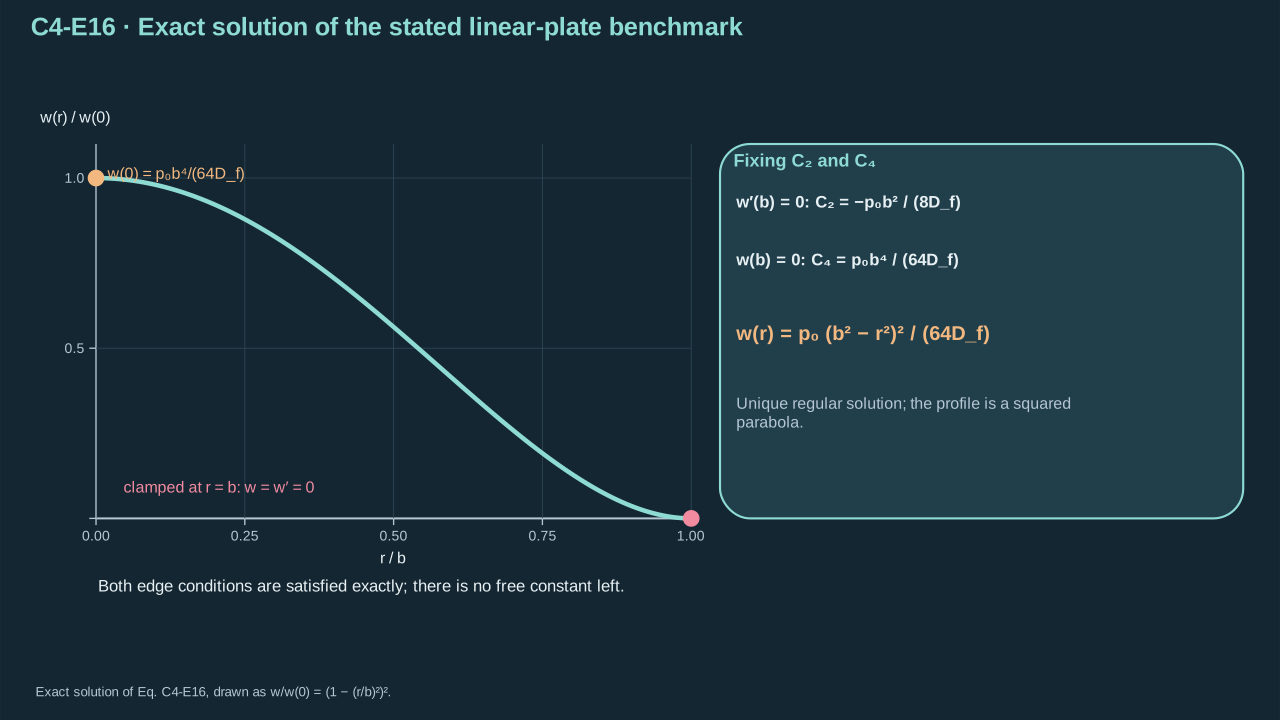
Conventions and conditions. The prime denotes d/dr; ⇒ denotes the algebraic consequence of each clamped boundary condition; Subscripts 2 and 4 label constants, and f labels film.
约定与条件。 撇号表示d/dr;⇒表示各夹持边界条件的代数结果;下标2与4标识常数,f表示薄膜。
(C4-E16) · Exact solution of the stated linear-plate benchmark
Applying both edge conditions fixes the unique regular blister profile.
同时应用两个边缘条件,确定唯一正则鼓泡轮廓。
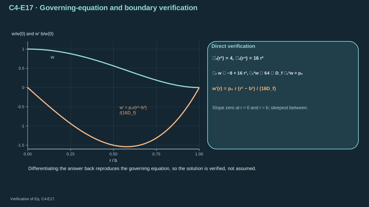
Step 12 — Substitute the solution to check it. Radial Laplacian of radius² is four. That of radius⁴ is sixteen × radius². Applying twice gives sixty-four. Edge displacement and slope vanish. Positive pressure opens the center; larger stiffness reduces opening. Units are Pa × m⁴/(N m) = m. MIT Lecture 7, Eq. 7.24 gives the same clamped-circle solution.
Direct radial differentiation verifies the pressure balance and regular clamped profile.
直接径向求导可检验压力平衡及正则夹持轮廓。
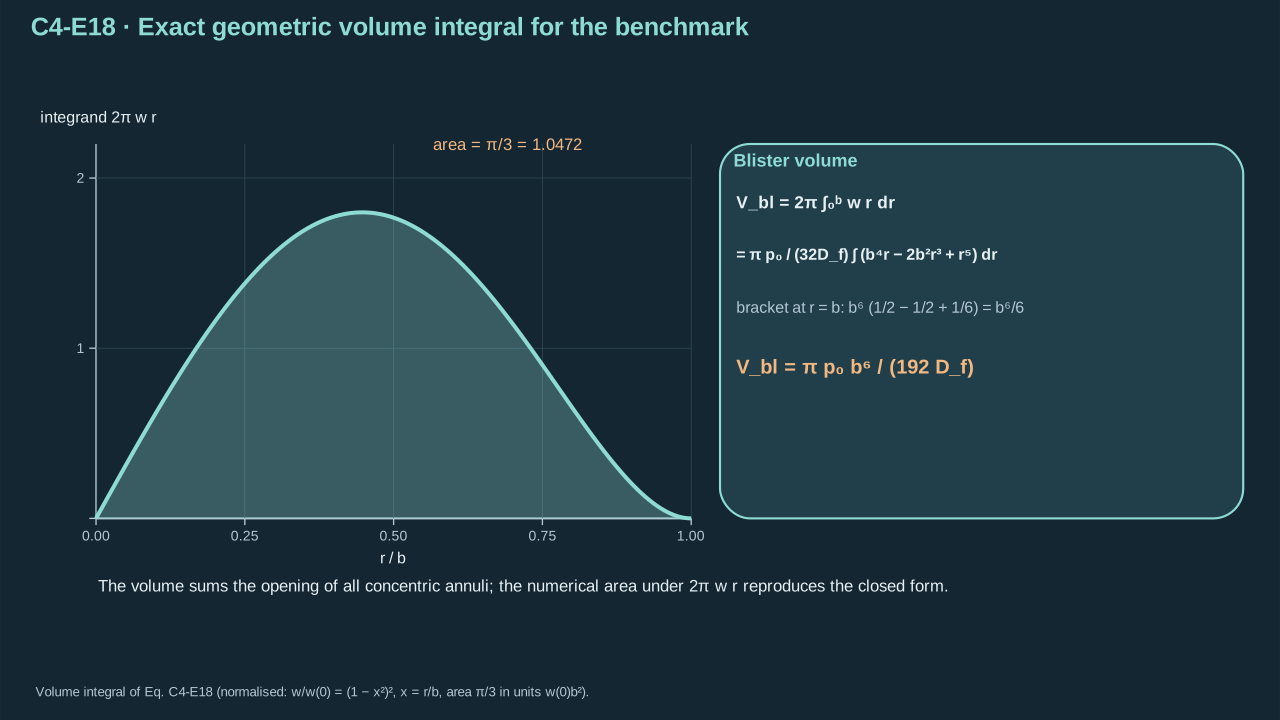
Step 13 — Integrate opening for cavity volume. The axisymmetric area element includes radius × radial increment. Expand the profile square and integrate each power. Evaluate both limits. The first two endpoint terms cancel, leaving the sixth-power term.
Conventions and conditions.∫ is radial integration; Subscript bl labels the blister; superscripts on lengths are powers; []0b denotes antiderivative at the upper endpoint minus its value at zero.
Blister volume sums the opening of all concentric annuli.
鼓泡体积等于各同心圆环张开贡献之和。
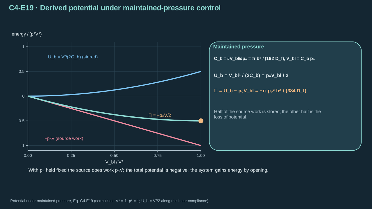
Step 14 — Include reservoir work in potential. At fixed crack radius, volume is linear in pressure. Elastic storage is half pressure × volume. Reservoir potential is minus pressure × volume. Their sum is minus the half-product. Omitting reservoir work reverses the pressure-controlled driving-force sign.
Cb>0 is blister volume compliance (m³ Pa⁻¹), defined by the pressure derivative at fixed radius, including the regular zero-load value
Cb>0为鼓泡体积柔度(m³ Pa⁻¹),由固定半径下的压力导数定义,包含正则零载荷值
Vbl≥0 is added volume (m³)
Vbl≥0为新增体积(m³)
p0≥0 maintained pressure (Pa)
p0≥0为恒定压力(Pa)
b>0 crack radius (m)
b>0为裂纹半径(m)
Df>0 bending stiffness (N m)
Df>0为弯曲刚度(N m)
Ub is stored plate bending energy (J)
Ub为板弯曲储能(J)
P plate-plus-pressure-reservoir potential (J)
P为板与恒压储库的总势能(J)
v a dummy volume along the fixed-radius elastic loading curve (m³), with dv its element (m³)
v为固定半径弹性加载曲线上的虚拟体积变量(m³)
dv — Dummy-volume integration element (m³)
dv — 体积哑变量积分微元(m³)
Conventions and conditions.∂/∂p0 is the pressure derivative; the vertical bar holds radius fixed; ∫ integrates that loading curve; Subscripts b and bl label blister compliance/bending and blister volume, respectively; the meanings are explicitly fixed here; No crack-area variation is taken during the loading-curve integral; For positive pressure, compliance also equals volume divided by pressure; at zero pressure the derivative avoids division by zero.
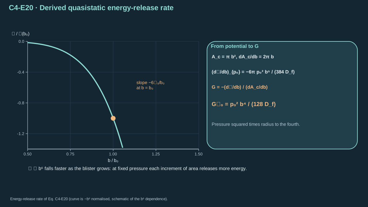
P total potential including maintained pressure (J)
P为包含恒压源的总势能(J)
p0 fixed pressure difference (Pa)
p0为固定压差(Pa)
Df bending stiffness (N m)
Df为弯曲刚度(N m)
Gp0 is energy-release rate under that control (J m⁻²)
Gp0为该控制方式下的能量释放率(J m⁻²)
Conventions and conditions.d/db differentiates in radius; the vertical bar and subscript p0 indicate held pressure; Subscript c labels crack area; all length superscripts are powers; Positive b makes the area derivative nonzero.
Geometry and compliance convert pressure into fracture energy per area.
几何与柔度将压力转换为单位面积断裂能。
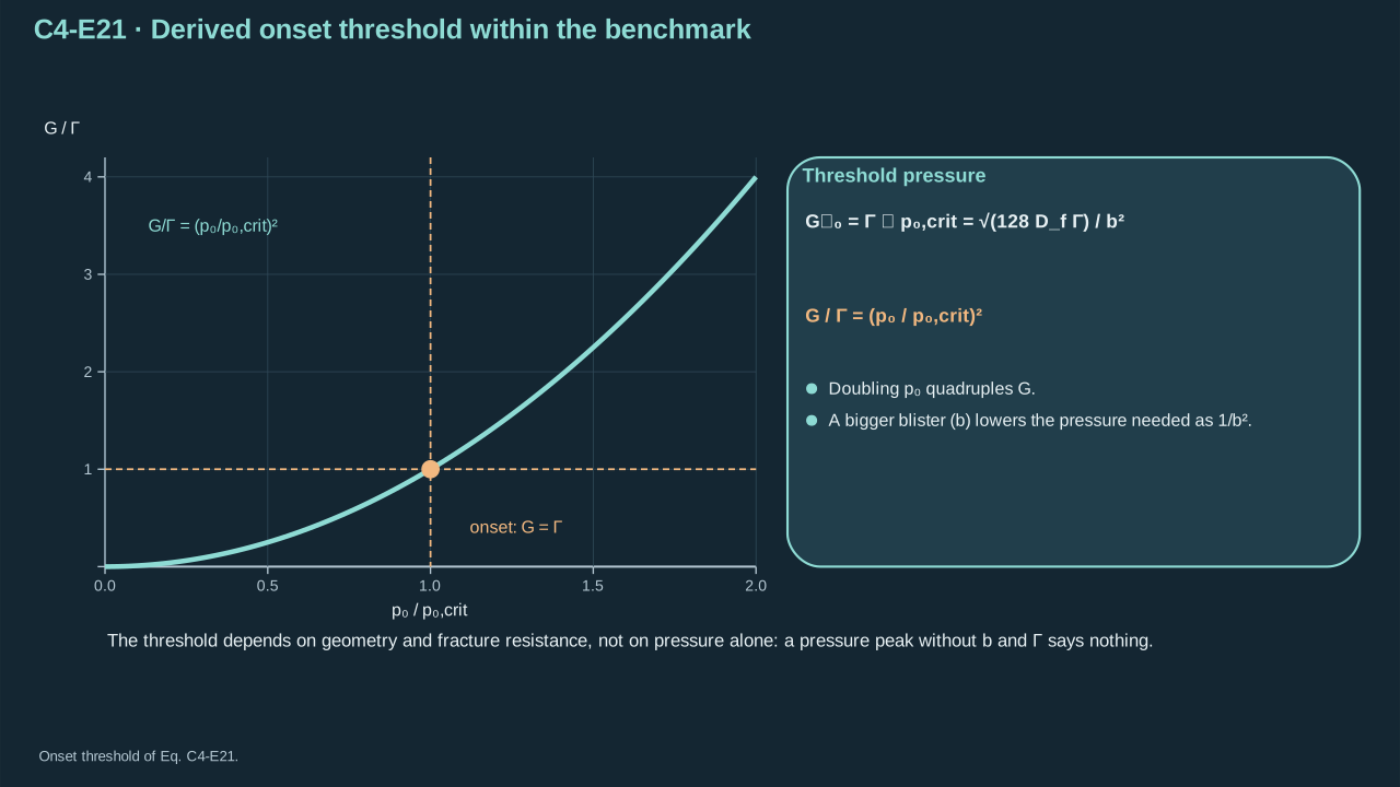
Symbols before Eq. (C4-E21).
式(C4-E21)前的符号定义。
First individual definition第一项单独定义
Second individual definition第二项单独定义
p0,crit>0 is critical maintained pressure (Pa) for constant fracture resistance Γ>0 (J m⁻²)
p0,crit>0为恒定断裂阻力Γ>0(J m⁻²)对应的临界恒压(Pa)
Df>0 is bending stiffness (N m)
Df>0为弯曲刚度(N m)
b>0delamination radius (m)
b>0为脱层半径(m)
p0≥0 applied maintained pressure (Pa)
p0≥0为外加恒压(Pa)
Gp0 the corresponding energy-release rate (J m⁻²)
Gp0为相应能量释放率(J m⁻²)
Γ — Practical interfacial fracture energy (J m⁻²)
Γ — 实际界面断裂能(J m⁻²)
Conventions and conditions. is the positive root; subscript crit labels the onset threshold; The quotient Gp0/Γ is dimensionless; This onset criterion assumes an existing crack and the quasistatic bending model.
(C4-E21) · Derived onset threshold within the benchmark
基准模型内推导的起始阈值
p0,crit=b2128DfΓ,ΓGp0=(p0,critp0)2
The pressure threshold depends on crack geometry and fracture resistance, not pressure alone.
压力阈值取决于裂纹几何及断裂阻力,而非压力本身。
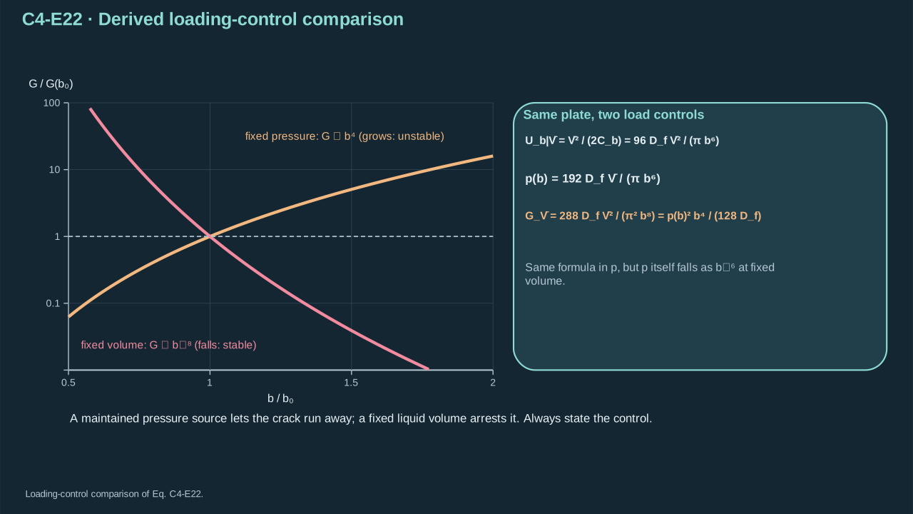
Step 16 — Change to fixed volume. Remove continuing reservoir work and eliminate pressure through compliance. Differentiate plate storage at fixed volume. Reinsert instantaneous pressure for comparison. The same state gives the same instantaneous expression. Radius growth increases fixed-pressure driving and decreases fixed-volume driving. Constant resistance therefore gives different stability under these controls. A sealed PFC cavity has evolving mass and temperature. Its trajectory needs a thermodynamic closure.
GVˉ — Energy-release rate at fixed added volume (J m⁻²)
GVˉ — 固定新增体积下的能量释放率(J m⁻²)
Gp0 — Energy-release rate at fixed maintained pressure (J m⁻²)
Gp0 — 固定恒定压力下的能量释放率(J m⁻²)
p0 is maintained pressure (Pa)
p0为恒定压力(Pa)
π the circle constant, and ∝ means proportional at fixed other parameters (dimensionless)
π为圆周率,∝表示其他参数固定时成正比(无量纲)
Conventions and conditions.d/db is radius differentiation holding Vˉ fixed; The bar labels controlled volume, not averaging; The fixed-volume system here supplies no additional pressure-source work.
Fixed pressure and fixed volume lead to opposite changes in driving force as the crack grows.
裂纹扩展时,恒压与恒容控制使驱动力发生相反变化。
Blister calculation
鼓泡计算
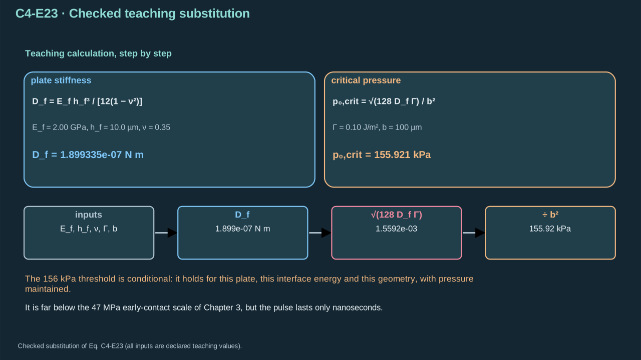
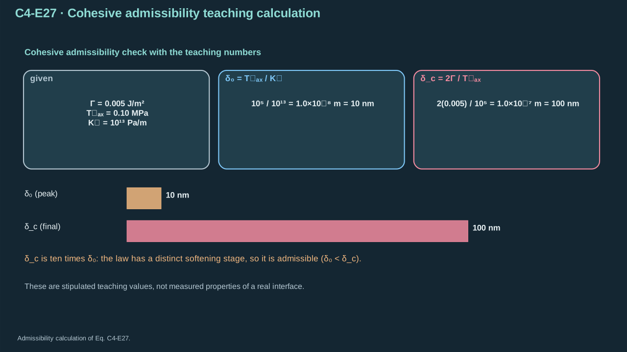
Prescribe modulus 2 GPa, thickness 10 μm, Poisson ratio 0.35, crack radius 100 μm and fracture energy 0.10 J m⁻². These source-course inputs describe the illustrative plate. They do not specify the later 1 μm payload or PVC formulation. Convert thickness to meters before cubing. Evaluate stiffness and the positive onset root.
p0,crit the positive critical maintained pressure (Pa)
p0,crit为正临界恒压(Pa)
Conventions and conditions. The substituted teaching Young’s modulus is 2.00×10⁹ Pa, thickness 10.0×10⁻⁶ m, Poisson’s ratio 0.35, crack radius 100×10⁻⁶ m, and fracture resistance 0.10 J m⁻²; Pa, N, m, J and kPa denote pascal, newton, metre, joule and kilopascal; is the positive root; superscripts are powers; Subscript f labels the film and crit the onset threshold.
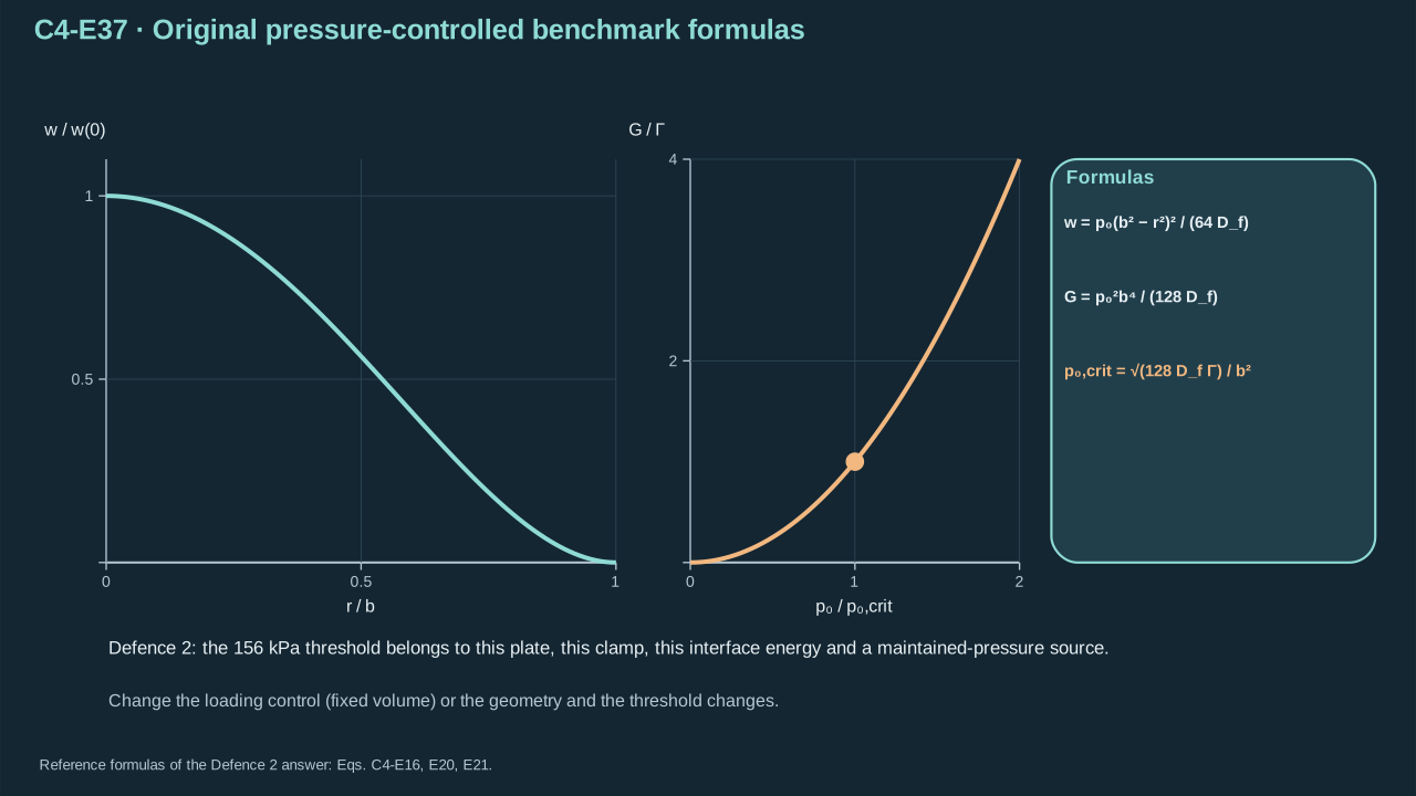
The stated plate and interface yield a conditional 156 kPa maintained-pressure threshold.
所给薄板与界面产生约156 kPa的条件性恒压阈值。
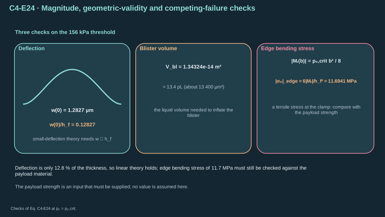
Check opening, volume and stress at onset. Edge moment magnitude is pressure × radius²/8. Outer-surface bending stress is six × moment/thickness². The hypothetical plate reaches about 11.7 MPa edge stress. Allowable strength is missing. Thickness/radius is 0.10. Finite-thickness error requires assessment before claiming accuracy.
Conventions and conditions. Subscript edge labels its outer-surface value at the clamped edge; r labels radial direction; ∣∣ denotes magnitude; μm and MPa are micrometre and megapascal; This stress result uses the same linear isotropic plate assumptions.
A fracture threshold must be checked against deflection validity and payload bending stress.
断裂阈值必须同时检验挠度适用性与对象弯曲应力。
6. Cohesive strength and separation work
6. 内聚强度与分离功
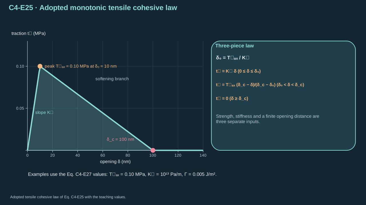
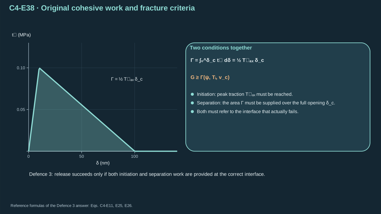
Step 17 — Adopt triangular tensile traction–separation behavior. Initial slope sets opening stiffness, peak sets initiation strength, and final opening completes separation. This is a declared interface model. Compression needs contact closure. Unloading needs elastic recovery and damage history. Mixed modes need a coupling law.
δ≥0 now denotes physical relative tensile opening (m), not variational notation
δ≥0此处表示物理相对拉伸张开(m),不再是变分符号
tn(δ) is tensile cohesive traction magnitude (Pa)
tn(δ)为拉伸内聚牵引幅值(Pa)
Kn>0 initial normal stiffness (Pa m⁻¹)
Kn>0为初始法向刚度(Pa m⁻¹)
Tmax>0 peak tensile traction (Pa)
Tmax>0为峰值拉伸牵引(Pa)
δ0=Tmax/Kn peak-traction opening (m)
δ0=Tmax/Kn为峰值牵引处张开(m)
δc>δ0 complete-separation opening (m)
δc>δ0为完全分离张开(m)
Conventions and conditions. Subscripts n, 0 and c label normal, peak onset and final separation; max labels the maximum; The law assumes monotonically increasing opening and a strictly positive softening interval; Compression and unloading are not specified by this formula.
The traction–separation curve contains strength, stiffness and a finite separation distance.
牵引—分离曲线包含强度、刚度及有限分离距离。
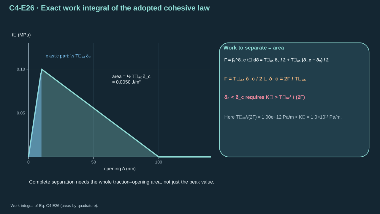
Step 18 — Integrate ascending and descending branches. Each contributes one triangle area. With admissible opening order, their sum depends on peak traction and final opening. Units are Pa m = J m⁻². Peak location still affects stiffness and initiation dynamics.
步骤 18——积分上升与下降分支。每段贡献一个三角形面积。张开顺序允许时,总面积取决于峰值牵引及最终张开。单位为 Pa m = J m⁻²。峰值位置仍影响刚度及起始动力学。
Symbols before Eq. (C4-E26).
式(C4-E26)前的符号定义。
First individual definition第一项单独定义
Second individual definition第二项单独定义
Γ>0 is the fracture energy of the adopted monotonic law (J m⁻²)
Γ>0为所采用单调关系的断裂能(J m⁻²)
δ tensile opening integration variable (m)
δ为拉伸张开积分变量(m)
dδ its element (m)
dδ为其微元(m)
tn is tensile cohesive traction (Pa)
tn为拉伸内聚牵引(Pa)
Kn>0 initial stiffness (Pa m⁻¹)
Kn>0为初始刚度(Pa m⁻¹)
Tmax>0 peak traction (Pa)
Tmax>0为峰值牵引(Pa)
δ0 opening at the peak (m)
δ0为峰值处张开(m)
δc>δ0 final separation opening (m)
δc>δ0为最终分离张开(m)
Conventions and conditions.∫ integrates traction against opening; endpoint brackets mean upper minus lower value; Subscripts n, 0, c and max label normal, peak onset, final separation and maximum; The last inequality enforces a nonzero softening branch; it is a model-admissibility condition.
Complete separation needs the entire traction–opening area, not merely the peak value.
完全分离需要完整牵引—张开曲线面积,而不仅仅达到峰值。
Symbols before Eq. (C4-E27).
式(C4-E27)前的符号定义。
First individual definition第一项单独定义
Second individual definition第二项单独定义
Γ is assumed fracture energy (J m⁻²)
Γ为假设断裂能(J m⁻²)
Tmax assumed peak tensile traction (Pa)
Tmax为假设峰值拉伸牵引(Pa)
Kn assumed initial normal stiffness (Pa m⁻¹)
Kn为假设初始法向刚度(Pa m⁻¹)
δ0 peak-traction opening (m)
δ0为峰值牵引处张开(m)
δc final tensile separation (m)
δc为最终拉伸分离(m)
Conventions and conditions. MPa and nm denote megapascal and nanometre; ⇒ denotes substitution into the triangular law; These are separate illustrative cohesive parameters, not measurements of the film release interface; Subscripts max, n, 0 and c identify peak, normal, peak opening and complete opening.
The example has distinct peak and final separation openings.
本例具有不同的峰值张开与最终分离张开。
7. Array-to-film calculation
7. 阵列至薄膜计算
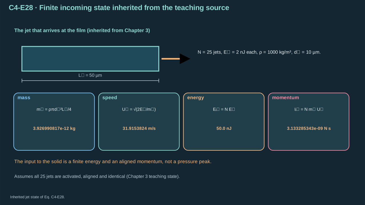
Step 19 — Carry forward the finite source. Chapter 2’s inventory feeds 25 independent Chapter 3 cells. Patterned/addressed illumination gives equal prescribed allocation. Total absorbed energy is 10 μJ. Declared jet conversion 0.005 gives 50 nJ kinetic energy. Each jet has density 1000 kg m⁻³, diameter 10 μm and length 50 μm. Recompute mass and momentum without rounded speed. Separate cells carry no interacting-bubble multiplier.
Conventions and conditions. is the positive root; Subscripts j and in label single jet and incoming array; nJ is nanojoule; Simultaneous aligned arrival is assumed for the directional sum, but pressure fields are not added as N times a peak.
Finite jet energy and aligned momentum provide the input to solid coupling.
有限射流能量与同向动量提供固体耦合输入。
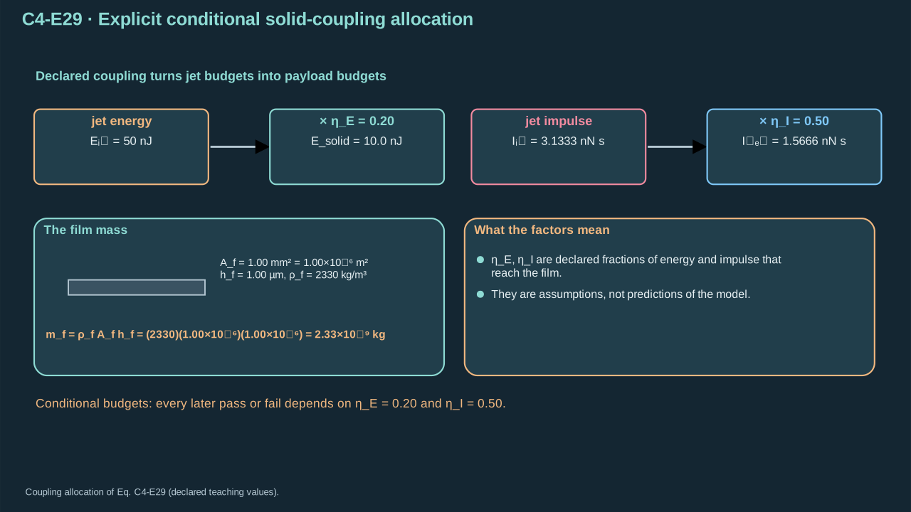
Step 20 — Declare solid coupling. Payload area is 1 mm², thickness 1 μm and density 2330 kg m⁻³. It starts at rest without stored recoverable energy. Assign 20% jet energy to deformation, release and departure. Assign 50% aligned momentum as net opening-direction payload impulse after reactions. Both fractions require measurement or coupled calculation. Boiling point and rigid-contact pressure leave them unresolved.
ηE=0.20 a dimensionless energy-allocation assumption
ηE=0.20为无量纲能量分配假设
Inet is assigned net opening-direction payload impulse after all load-path reactions (N s)
Inet为考虑全部传力路径反作用后的净张开方向对象冲量(N s)
Iin aligned incoming momentum (N s)
Iin为同向入射动量(N s)
ηI=0.50 a dimensionless impulse assumption
ηI=0.50为无量纲冲量假设
Conventions and conditions. Labels f, in, solid, net, E and I identify film, incoming, useful solid allocation, net, energy and impulse; The numerical first-row factors represent density, area and thickness in SI units.
Declared coupling converts incoming jet budgets into conditional payload budgets.
明确声明的耦合将入射射流预算转换为条件性对象预算。
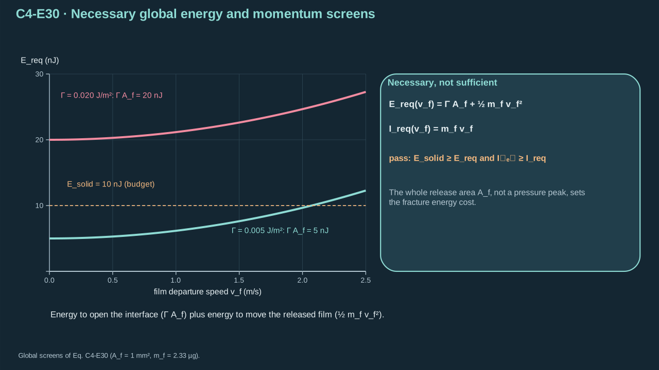
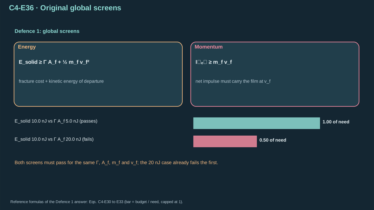
Step 21 — Apply global necessary conditions. Separation costs fracture energy × intended area. Minimum translation costs half mass × minimum speed². Net impulse must reach mass × minimum speed. Residual bending, rotation, loss and competing fracture add demands. Failure excludes this assumed case. Passing leaves full transfer unresolved. Exact complete impulse from rest fixes final center-of-mass speed.
Ereq(vf) is minimum fracture-plus-translation energy (J)
Ereq(vf)为最低断裂加平动能量(J)
Ireq(vf) required net impulse for the minimum departure speed (N s)
Ireq(vf)为达到最低离开速度所需净冲量(N s)
vf≥0 that required speed (m s⁻¹)
vf≥0为所需速度(m s⁻¹)
mf>0 payload mass (kg)
mf>0为对象质量(kg)
Af full intended release area (m²)
Af为全部目标释放面积(m²)
Γ≥0 assumed uniform fracture energy (J m⁻²)
Γ≥0为假设均匀断裂能(J m⁻²)
Esolid is assigned available solid energy (J)
Esolid为指定可用固体能量(J)
Inet is net opening-direction impulse after interface/support reactions (N s)
Inet为考虑界面/支承反作用后的净张开方向冲量(N s)
Conventions and conditions. Subscripts req, f, solid and net identify required, payload, useful solid and net quantities; The inequalities are necessary under the stated zero-initial-energy/no-additional-source assumptions; they are not spatial fracture solutions.
The full intended release area, not a pressure peak, determines the fracture-energy cost.
决定断裂能消耗的是全部目标释放面积,而非压力峰值。
Symbols before Eq. (C4-E31).
式(C4-E31)前的符号定义。
First individual definition第一项单独定义
Second individual definition第二项单独定义
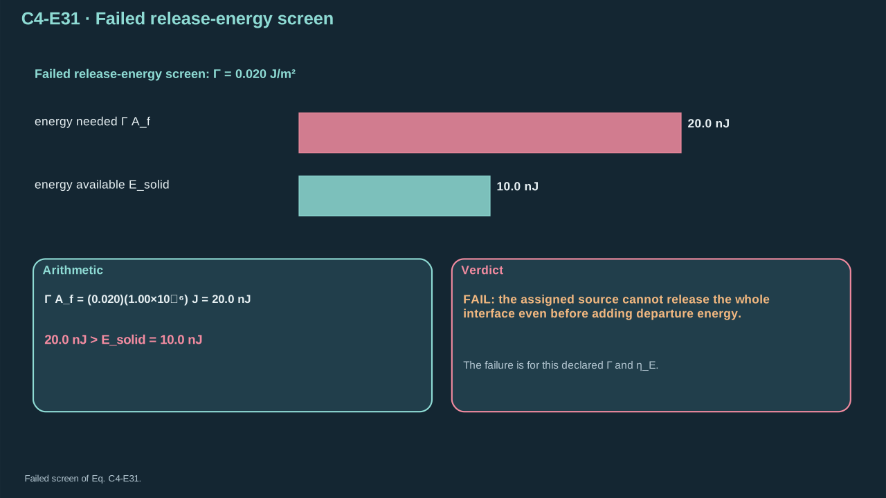
Γ is assumed uniform release fracture energy (J m⁻²)
Γ为假设均匀释放断裂能(J m⁻²)
Af=1.00×10⁻⁶ m² intended full release area (m²)
Af=1.00×10⁻⁶ m²为全部目标释放面积(m²)
Esolid=10.0 nJ assigned available solid energy (J)
Esolid=10.0 nJ为指定可用固体能量(J)
Conventions and conditions. nJ is nanojoule; ⇒ denotes numerical substitution; The comparison assumes no initially stored recoverable energy and no additional post-impact source; Subscript f labels film area, and solid labels the assigned useful energy.
The assigned source cannot release the whole interface even before departure energy is added.
即使尚未计入离开动能,所指定源也无法释放整个界面。
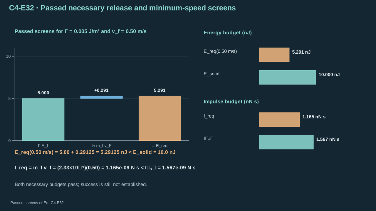
The stated energy failure excludes that case. The 47.23 MPa local transient creates no extra energy. Its footprint cannot automatically cover 1 mm² or sustain full-duration loading. Local damage is possible. Now change fracture energy to 0.005 J m⁻². Require minimum departure speed 0.50 m s⁻¹. Keep incoming jets and coupling fixed, then repeat both screens.
Γ=0.005 J m⁻² is the changed teaching fracture energy
Γ=0.005 J m⁻²为改变后的教学断裂能
Af=1.00×10⁻⁶ m² is release area (m²)
Af=1.00×10⁻⁶ m²为释放面积(m²)
mf=2.33×10⁻⁹ kg is payload mass (kg)
mf=2.33×10⁻⁹ kg为对象质量(kg)
vf=0.50 m s⁻¹ is minimum required departure speed
vf=0.50 m s⁻¹为最低所需离开速度
Ereq is minimum fracture-plus-translation energy (J)
Ereq为最低断裂加平动能(J)
Ireq required net impulse (N s)
Ireq为所需净冲量(N s)
Inet=1.566642672×10⁻⁹ N s the assigned actual net impulse
Inet=1.566642672×10⁻⁹ N s为指定实际净冲量
Conventions and conditions. nJ is nanojoule; Subscripts req, f and net label required, payload and net; The 10.0 nJ comparator is assigned solid energy; The first-row numbers are SI mass and speed.
Reducing the assumed fracture cost allows the necessary budgets to pass.
降低假设断裂消耗后,必要预算可以通过。
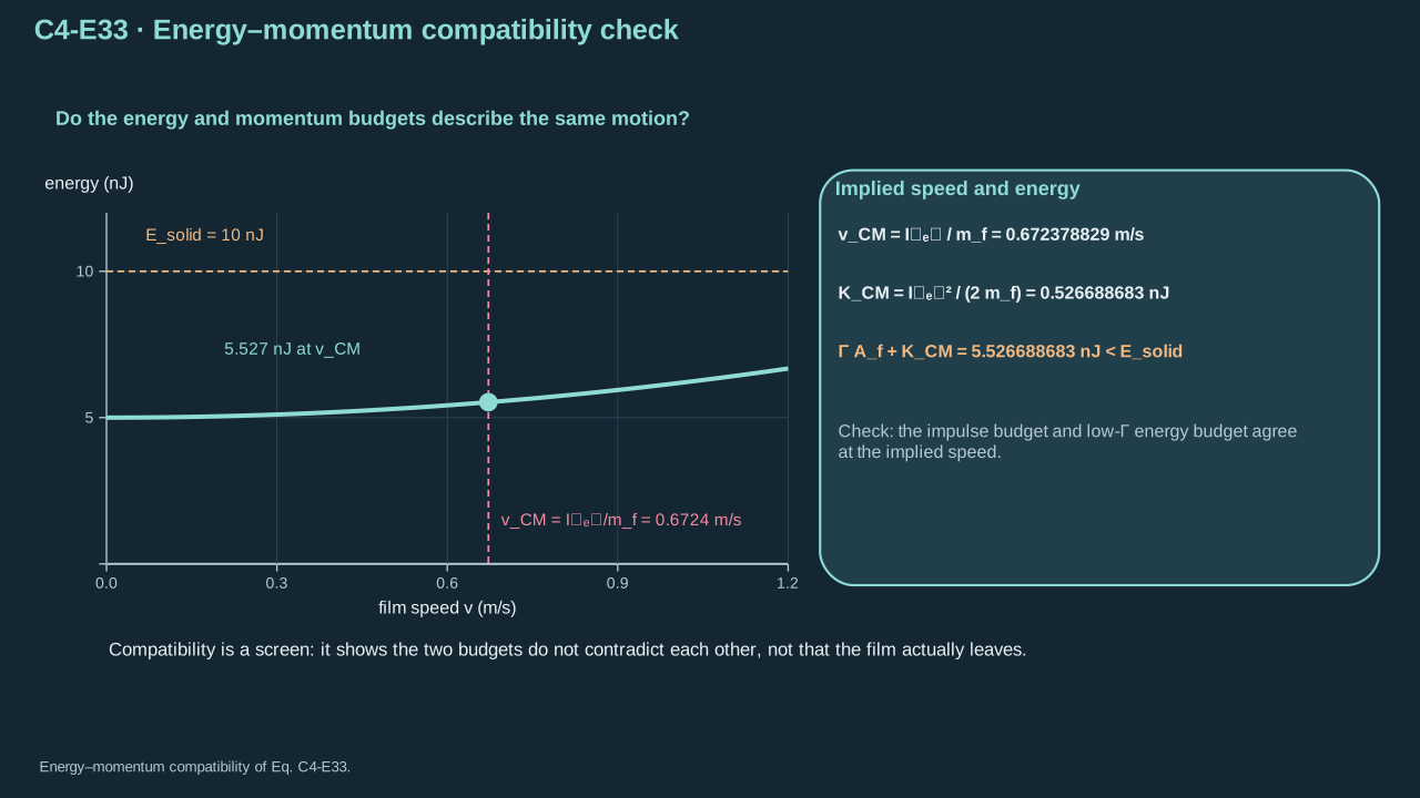
Step 22 — Match energy to exact impulse. Complete assigned impulse gives final speed 0.67238 m s⁻¹. This exceeds the 0.50 m s⁻¹ minimum. Its kinetic energy is 0.52669 nJ; minimum-speed energy is 0.29125 nJ. Adding actual kinetic energy still fits the 10 nJ low-fracture budget. Exact 0.50 m s⁻¹ would require counter-impulse or different coupling. Energy and momentum must share a physical force path.
步骤 22——使能量与精确冲量一致。完整分配冲量给出最终速率 0.67238 m s⁻¹,高于 0.50 m s⁻¹ 最低要求。对应动能为 0.52669 nJ,最低速率动能为 0.29125 nJ。计入实际动能后仍满足 10 nJ 低断裂能预算。精确 0.50 m s⁻¹ 需反向冲量或不同耦合。能量和动量须对应同一实际传力路径。
Symbols before Eq. (C4-E33).
式(C4-E33)前的符号定义。
First individual definition第一项单独定义
Second individual definition第二项单独定义
vCM is actual final centre-of-mass speed (m s⁻¹) if the specified Inet is the complete net impulse from rest (N s)
Inet — Net opening-direction impulse after all load-path reactions (N s)
Inet — 考虑全部载荷路径反作用后的净张开方向冲量(N s)
Conventions and conditions. CM labels centre of mass and net labels impulse after all reactions; nJ denotes nanojoule; Rotation, shape motion and dissipation still require additional positive energy beyond the terms shown.
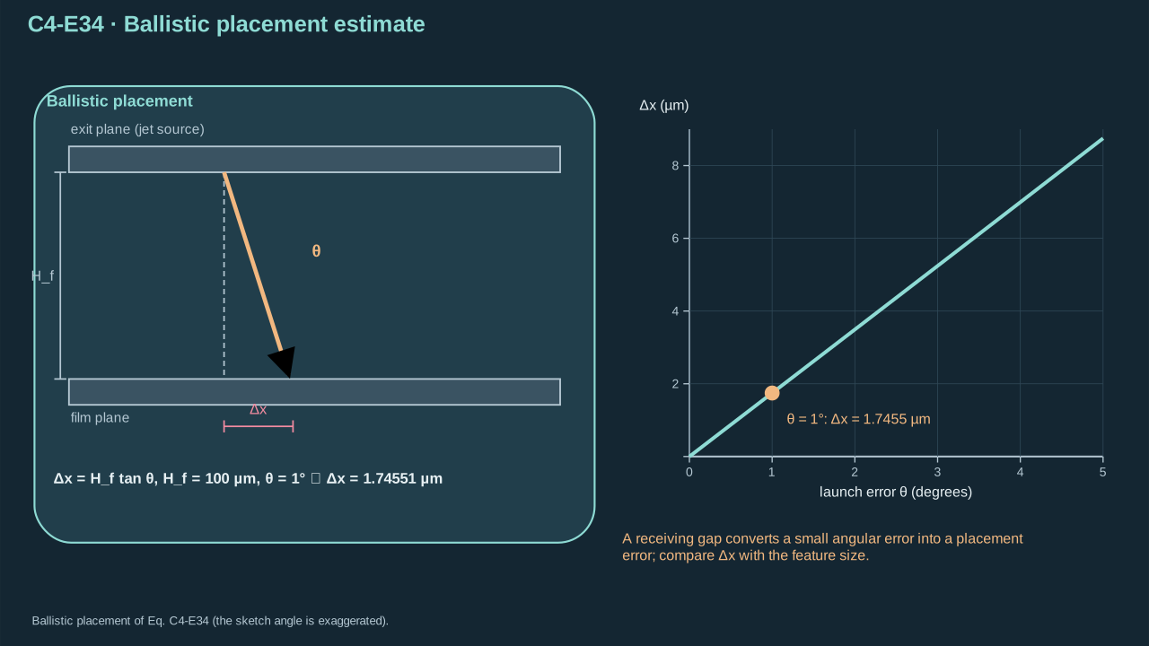
Step 23 — Track payload flight after release. With negligible drag and gravity, lateral offset equals normal gap × tangent of departure angle. Use payload gap rather than liquid-jet gap. Array nonuniformity can add torque despite sufficient net impulse. The receiver must arrest motion, avoid damage and rebound, and provide final adhesion.
θ∈(−π/2,π/2) departure angle relative to the target normal (rad)
θ∈(−π/2,π/2)为相对目标法向的离开角(rad)
Conventions and conditions.tan is tangent; the numerical angle is converted from degrees to radians for evaluation; μm is micrometre and ⇒ denotes substitution; Subscript f labels film/payload flight, not liquid-jet travel; The relation assumes straight flight without significant drag, gravity or rotation-dependent aerodynamic force; Δ marks position difference.
A finite receiving gap converts angular error into placement error.
有限接收间隙将角度误差转换为落位误差。
Cooling, condensation, remaining inventory, shell integrity and trapped gas set the next shot. Persistent cavities can change absorption, wetting and transmission. Repeatable transfer requires activation, useful output, selective release, survival, landing and reset. Report single-shot pressure records separately from the repeatable transfer window.
Measure deposited energy and activation statistics. Track cavity shape, lifetime and arriving jet mass, speed and direction. Record exposed and buried load histories, PVC/film motion and crack growth. Verify final integrity, position and next-shot state. Each missing link needs its corresponding measurement or model.
Trace a 47 MPa impact through the film/PVC stack. What limits release?
追踪 47 MPa 撞击在薄膜/PVC 叠层中的传递。什么限制释放?
Explain the mechanism, assumptions, and limits in your own words.
用自己的话解释机制、假设与限制。
Reference answer and mastery criteria参考答案与掌握标准
Symbols before Eq. (C4-E35).
式(C4-E35)前的符号定义。
First individual definition第一项单独定义
Second individual definition第二项单独定义
tl — Liquid traction on the solid (Pa)
tl — 液体作用于固体的牵引(Pa)
Tl liquid stress tensor (Pa)
Tl为液体应力张量(Pa)
nf solid-to-liquid unit normal (dimensionless)
nf为固体指向液体的单位法向(无量纲)
Il applied liquid impulse (N s)
Il为液体外加冲量(N s)
Wl delivered work (J)
Wl为传递功(J)
Af(t) is loaded surface (m²)
Af(t)为受载表面(m²)
dA its element (m²)
dA为其微元(m²)
vf surface velocity (m s⁻¹)
vf为表面速度(m s⁻¹)
ta — Load-event start time (s)
ta — 载荷事件开始时刻(s)
tb — Load-event end time (s)
tb — 载荷事件结束时刻(s)
t — Time (s)
t — 时间(s)
dt — Time integration element (s)
dt — 时间积分微元(s)
Conventions and conditions.∫ means surface/time integration; the dot denotes a vector projection; Subscripts l and f label liquid and film; The same identities first load PVC if it is the exposed layer; ta<tb fixes the integration interval..
Reference answer: pressure, impulse and work describe different parts of the transmission path.
参考答案:压力、冲量与功描述传递路径中的不同部分。
Symbols before Eq. (C4-E36).
式(C4-E36)前的符号定义。
First individual definition第一项单独定义
Second individual definition第二项单独定义
Esolid — Assigned useful solid-energy budget (J)
Esolid — 指定的有效固体能量预算(J)
Γ uniform release fracture energy (J m⁻²)
Γ为均匀释放断裂能(J m⁻²)
Af intended full release area (m²)
Af为全部目标释放面积(m²)
mf payload mass (kg)
mf为对象质量(kg)
vf minimum required departure speed (m s⁻¹)
vf为最低所需离开速度(m s⁻¹)
Inet net opening impulse after all reactions (N s)
Inet为考虑全部反作用后的净张开冲量(N s)
Conventions and conditions. The payload initially rests and has no additional recoverable source; Subscripts solid, f and net label useful solid allocation, payload and net impulse.
Reference answer: finite energy and net impulse must reach the intended interface.
参考答案:有限能量与净冲量必须到达目标界面。
The 47.23 MPa scale describes initial local compression at a rigid receiver. Footprint, duration and transmission still require calculation. Twenty-five jets carry 50 nJ; assigned useful solid energy is 10 nJ. Releasing 1 mm² at 0.020 J m⁻² costs 20 nJ before translation. This case fails its energy condition. Direct impact first loads film; intact PVC first carries the load. Film loading follows PVC motion and contact. A lower-fracture case still needs crack coverage and payload integrity.
Distinguish local compressive pressure from opening traction, impulse and delivered work.
区分局部压缩压力、张开牵引、冲量与传递功。
Explain why the stated 10 nJ budget cannot pay the 20 nJ full-area release cost.
解释为什么所给10 nJ预算无法支付20 nJ整面积释放消耗。
Trace direct and PVC-mediated force paths, identify unknown transmission, and retain spatial/competing-failure checks.
追踪直接及PVC介导传力路径,指出未知传递关系,并保留空间/竞争失效检验。
When does the 156 kPa blister threshold apply?
156 kPa 鼓泡阈值适用于哪些条件?
Explain the mechanism, assumptions, and limits in your own words.
用自己的话解释机制、假设与限制。
Reference answer and mastery criteria参考答案与掌握标准
Symbols before Eq. (C4-E37).
式(C4-E37)前的符号定义。
First individual definition第一项单独定义
Second individual definition第二项单独定义
w(r) — Blister opening displacement (m)
w(r) — 鼓泡张开位移(m)
r∈[0,b] radial position (m)
r∈[0,b]为径向位置(m)
b>0 existing circular crack radius (m)
b>0为预存圆裂纹半径(m)
p0≥0 uniform maintained pressure difference (Pa)
p0≥0为均匀恒定压差(Pa)
Df>0 linear plate bending stiffness (N m)
Df>0为线性薄板弯曲刚度(N m)
Gp0 fixed-pressure energy-release rate (J m⁻²)
Gp0为恒压能量释放率(J m⁻²)
Γ>0 constant fracture resistance (J m⁻²)
Γ>0为恒定断裂阻力(J m⁻²)
p0,crit positive onset pressure (Pa)
p0,crit为正起始压力(Pa)
Conventions and conditions. is the positive root; Subscripts f, 0 and crit denote film, maintained load and threshold; These expressions require regular centre and a clamped crack edge, quasistatic bending, and negligible stretching/pretension.
Reference answer: this pressure threshold follows a particular geometry and loading control.
参考答案:此压力阈值源于特定几何及加载控制。
The blister threshold follows from the clamped-plate solution, volume integration and reservoir work. Differentiate total potential by crack area. Assume an existing circular crack, slow uniform bending, negligible stretching, pretension and inertia. A brief local jet needs a different loading history. Intact PVC also changes the loaded structure. Fixed pressure increases driving with crack radius. Fixed volume lowers pressure and driving during growth. A sealed PFC cavity needs evolving pressure, volume and temperature. Rapid release needs transmitted traction, inertia, crack kinetics and energy balance. Check payload stress alongside interface release.
Identify the clamped existing crack, uniform maintained pressure and quasistatic small-deflection assumptions.
指出夹持预裂纹、均匀恒压及准静态小挠度假设。
Explain why short/localized loads, fixed volume, sealed thermodynamics or PVC transmission require another calculation.
解释短时/局部载荷、恒容、封闭热力学或PVC传递为什么需要另一计算。
Both global screens pass. What measurements establish repeatable intact transfer?
两项整体筛选均通过。哪些测量能确立可重复完整转印?
Explain the mechanism, assumptions, and limits in your own words.
用自己的话解释机制、假设与限制。
Reference answer and mastery criteria参考答案与掌握标准
Symbols before Eq. (C4-E38).
式(C4-E38)前的符号定义。
First individual definition第一项单独定义
Second individual definition第二项单独定义
Γ — Practical interfacial fracture energy (J m⁻²)
Γ — 实际界面断裂能(J m⁻²)
δ physical opening integration variable (m)
δ为物理张开积分变量(m)
dδ its element (m)
dδ为其微元(m)
δc complete opening (m)
δc为完全张开(m)
tn tensile cohesive traction (Pa)
tn为拉伸内聚牵引(Pa)
Tmax peak tensile traction (Pa)
Tmax为峰值拉伸牵引(Pa)
G is energy available per new crack area (J m⁻²)
G为单位新增裂纹面积可用能量(J m⁻²)
ψ dimensionless mode mixture
ψ为无量纲模态混合参数
Ti interface temperature (K)
Ti为界面温度(K)
vc crack speed (m s⁻¹)
vc为裂纹速度(m s⁻¹)
Conventions and conditions. The half-product applies to the adopted triangular monotonic law; ∫ denotes opening integration; Subscripts n, c, i and max identify normal, crack/final opening, interface and maximum.
(C4-E38) · Original cohesive work and fracture criteria
原始内聚功与断裂判据
Γ=∫0δctn(δ)dδ=21Tmaxδc,G≥Γ(ψ,Ti,vc)
Reference answer: successful release requires both initiation and separation work at the correct interface.
参考答案:成功释放需要在正确界面上同时满足起始与分离功要求。
Symbols before Eq. (C4-E39).
式(C4-E39)前的符号定义。
First individual definition第一项单独定义
Second individual definition第二项单独定义
Esolid — Assigned useful solid-energy budget (J)
Esolid — 指定的有效固体能量预算(J)
Γfracture energy (J m⁻²)
Γ为断裂能(J m⁻²)
Af full release area (m²)
Af为全部释放面积(m²)
mf payload mass (kg)
mf为对象质量(kg)
vf minimum departure speed (m s⁻¹)
vf为最低离开速度(m s⁻¹)
Inet net opening impulse (N s)
Inet为净张开冲量(N s)
Δx is lateral payload offset (m)
Δx为对象横向偏移(m)
Hf normal payload flight gap (m)
Hf为对象法向飞行间隙(m)
θ departure angle relative to receiver normal, and tan tangent (rad)
θ为相对接收面法向的离开角,tan为正切(rad)
Conventions and conditions. The screens assume initial rest without another energy source; the placement relation assumes straight short flight; Subscripts solid, f and net label useful solid energy, payload and net impulse.
(C4-E39) · Original necessary operating-window checks
原始工作窗口的必要条件检验
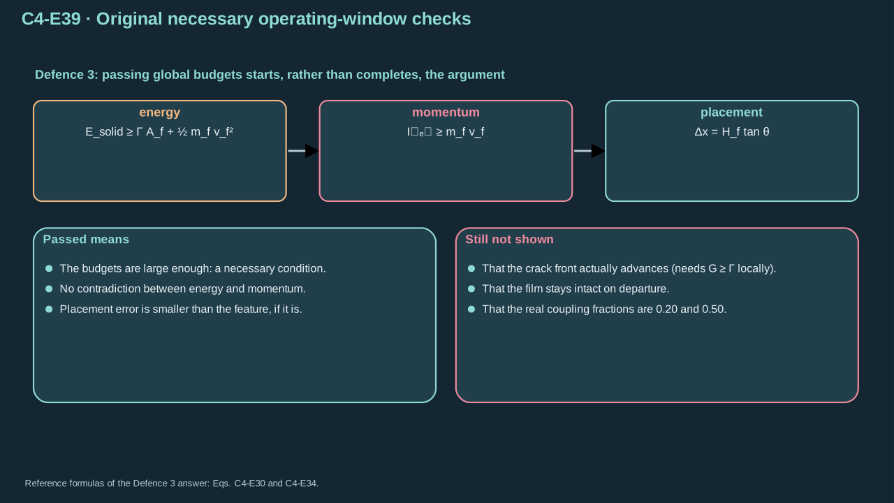
Esolid≥ΓAf+21mfvf2,Inet≥mfvf,Δx=Hftanθ
Reference answer: passing global budgets starts, rather than completes, the transfer argument.
参考答案:通过整体预算是转印论证的起点,而非终点。
The low-fracture case passes assigned energy and minimum-impulse conditions. Complete transfer: Not established. Missing: local initiation, full crack coverage and payload survival. Compression needs conversion into relative interface opening. Exclude unintended release, puncture, tearing and excessive bending. Keep exact impulse consistent with final translation. Then check tilt, flight, landing adhesion and rebound. Synchronize solid motion, crack growth and integrity measurements. Repeated shots require cooling, condensation and remaining-inventory checks. Report single-shot output separately from repeatable intact transfer.
Distinguish local strength initiation, full separation work and competing fracture paths.
区分局部强度起始、完整分离功及竞争断裂路径。
Keep energy and actual net impulse consistent and explain why spatial crack coverage and payload damage remain unresolved.
保持能量与实际净冲量相容,并解释为什么空间裂纹覆盖和对象损伤仍未确定。
Connect correct release to placement, landing and repeatable thermal/phase reset, proposing observations for the missing links.
将正确释放连接至落位、着陆及可重复热/相变复位,并为缺失环节提出观测。
Submit your three answers
提交三个回答
Answer in your own words, in either language. Paste your answers into the teaching chat. Review covers reasoning, assumptions, and limits. All three accepted answers establish chapter mastery.